
Magnetic resonance imaging apparatus, magnetic resonance imaging method and sensitivity distribution measuring apparatus

Inactive Publication Date: 2008-09-25
GE MEDICAL SYST GLOBAL TECH CO LLC
View PDF13 Cites 22 Cited by
  • Summary
  • Abstract
  • Description
  • Claims
  • Application Information

AI Technical Summary

Benefits of technology

[0034]According to the invention, there can be provided a magnetic resonance imaging apparatus, a magnetic resonance imaging method and a sensitivity distribution measuring apparatus each of which is capable of measuring a transmission sensitivity distribution with a high degree of accuracy and enhancing image quality.

Problems solved by technology

However, the surface coil has the characteristic that sensitivity to be received is lowered as the distance to the source of generation of each magnetic resonance signal in the subject increases, and a sensitivity distribution in the entire imaging area is not uniform spatially.
Therefore, there is a case where an image generated based on each magnetic resonance signal received by the surface coil will cause artifacts and hence image quality is degraded.
However, there is a case where upon imaging or photographing an imaging area of a subject, a high-frequency magnetic field formed by allowing an RF coil such as a body coil to transmit each RF pulse becomes ununiform in an imaging space due to a dielectric-constant effect.
Therefore, there is a case in which even when the actual scan image is corrected using the above reception sensitivity distribution, the artifacts cannot be removed sufficiently.
That is, there is a case where it is difficult to enhance the quality of the actual scan image due to a transmission sensitivity distribution being ununiform spatially.
Since, however, the method of the former (1) may be affected by physical characteristics such as a longitudinal relaxation time T1 at a target to be imaged, its horizontal relaxation time T2 and the like, and body motion, it may be difficult to calculate the transmission sensitivity distribution with a high degree of accuracy.
It is, however, not easy to calculate a transmission sensitivity distribution from each reference image in a pulse sequence of an FSE (Fast Spin Echo) system, an SSFP (Steady State Free Precession) system.
It is therefore difficult to calculate the transmission sensitivity distribution with a high degree of accuracy.
Since it is not easy to calculate each transmission sensitivity distribution with a high degree of accuracy in this way, there was a case in which it was difficult to enhance the quality of the actual scan image.

Method used


Image

  • Magnetic resonance imaging apparatus, magnetic resonance imaging method and sensitivity distribution measuring apparatus
  • Magnetic resonance imaging apparatus, magnetic resonance imaging method and sensitivity distribution measuring apparatus
  • Magnetic resonance imaging apparatus, magnetic resonance imaging method and sensitivity distribution measuring apparatus

Examples


Embodiment Construction

[0044]One example of an embodiment according to the invention will be explained below with reference to the accompanying drawings.

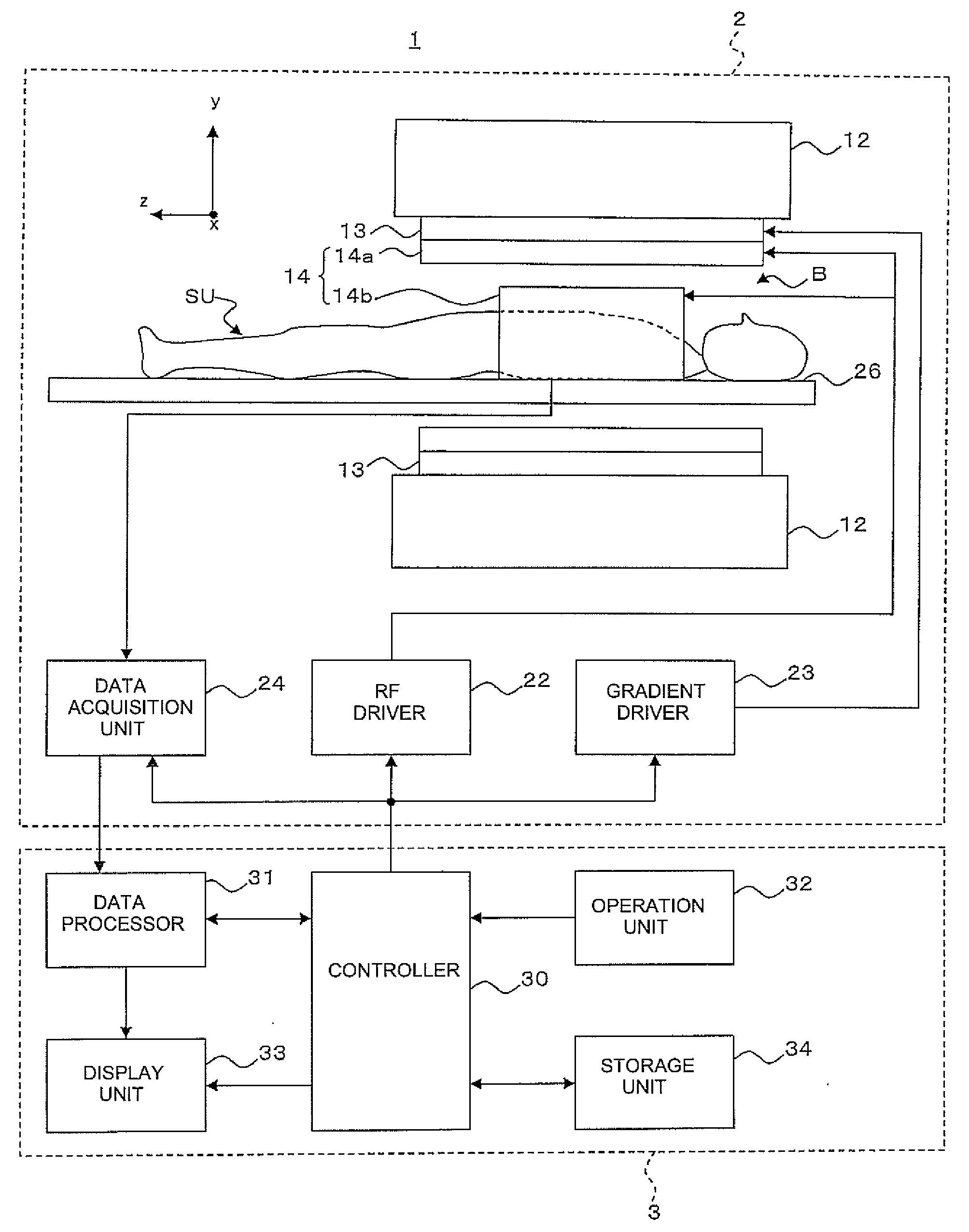
[0045]FIG. 1 is a configuration diagram showing the construction of a magnetic resonance imaging apparatus 1 illustrative of an embodiment according to the invention.

[0046]As shown in FIG. 1, the magnetic resonance imaging apparatus 1 has a scan section 2 and an operation console section 3.

[0047]Here, the scan section 2 has a static magnetic field magnet unit 12, a gradient coil unit 13, an RF coil unit or part 14, an RF driver 22, a gradient driver 23, a data acquisition unit 24 and a cradle 26 as shown in FIG. 1. As shown in FIG. 1, the operation console section 3 has a controller 30, a data processor 31, an operation unit 32, a display or display unit 33 and a storage unit 34.

[0048]As shown in FIG. 1, the scan section 2 includes an imaging space B which is formed with a static magnetic field and in which an imaging area containing a target for imaging ...


PUM


Abstract

A magnetic resonance imaging apparatus which executes a scan for allowing an RF coil unit to transmit RF pulses to an imaging area of a subject in a static magnetic filed space and allowing the RF coil unit to acquire magnetic resonance signals generated in the imaging area, includes: a scan section which executes, as the scan, each of an actual scan for acquiring the magnetic resonance signals as actual scan data and a reference scan for acquiring the magnetic resonance signals as reference scan data; an image reconstruction unit which reconstructs an actual scan image about the imaging area, based on the actual scan data and reconstructs a reference scan image about the imaging area, based on the reference scan data; a transmission sensitivity distribution calculating unit which calculates a transmission sensitivity distribution at the transmission of the RF pulses by the RF coil unit in the imaging area, based on the reference scan image and the actual scan image; and an image correcting unit which corrects the actual scan image using the transmission sensitivity distribution, wherein the transmission sensitivity distribution calculating unit includes: a division image generating part which executes image processing for dividing the first reference image by the second reference image, thereby generating a division image; a labeling information generating part which executes a labeling process on the division image thereby to generate labeling information about the division image; a segmentation process executing part which executes a segmentation process on the actual scan image, based on the labeling information thereby to extract a plurality of segments from the actual scan image; and a fitting processing part which calculates relational expressions indicative of relationships between pixel values of pixels constituting the segments and pixel positions thereof with respect to the segments extracted from the actual scan image, by performing a process for fitting to polynomial models, and wherein the transmission sensitivity distribution is calculated based on the relational expressions calculated by the fitting processing part.

Description

CROSS REFERENCE TO RELATED APPLICATIONS[0001]This application claims the benefit of Japanese Patent Application No. 2007-077513 filed Mar. 23, 2007, which is hereby incorporated by reference in its entirety.BACKGROUND OF THE INVENTION[0002]The field of the present invention relates to a magnetic resonance imaging apparatus, a magnetic resonance imaging method and a sensitivity distribution measuring apparatus. The present invention relates particularly to a magnetic resonance imaging apparatus, a magnetic resonance imaging method and a sensitivity distribution measuring apparatus each of which calculates a transmission sensitivity distribution at the transmission of each RF pulse to an imaging area by an RF coil unit.[0003]A magnetic resonance imaging apparatus has been used in various fields such as a medical field, an industrial field, etc.[0004]The magnetic resonance imaging apparatus includes an imaging space formed with a static magnetic field. An imaging area including a targe...

Claims


Application Information

Patent Timeline
IPC IPC(8): G01R33/56
CPCG01R33/56G01R33/5659G01R33/5617G01R33/5608
Inventor KABASAWA, HIROYUKI
Owner GE MEDICAL SYST GLOBAL TECH CO LLC
Learn More