
High speed solid cooking fuel igniter

a fuel igniter and high-speed technology, applied in the field of igniters, can solve the problems of large increase in the problem of charcoal/wood ignition, rare and awkward use, and devices lacking the ability to impart a natural wood smoke flavor

Inactive Publication Date: 2008-09-25
WARNER JON A
View PDF16 Cites 25 Cited by
  • Summary
  • Abstract
  • Description
  • Claims
  • Application Information

AI Technical Summary

Benefits of technology

[0007]In some embodiments, the device includes a closure mechanism, which in some embodiments is a breach-loading closure mechanism. The closure mechanism provides selective access to the kindling chamber for loading kindling, paper, or other starting fuels into the kindling chamber. The closure may also provide a seal, when in a closed configuration, to permit and/or maintain the increased air velocity, flow rat

Problems solved by technology

It is a popular activity to cook foods over a charcoal grill, but certain drawbacks to this process have led to the development of various gas fired barbeque products that mimic the effects of charcoal grilling.
In general, these devices lack the ability to impart a natural wood smoke flavor to the items being grilled.
It is possible to add wood chips to such grills, but this is seldom done and is in some cases awkward.
The problem of charcoal / wood ignition is greatly increased as one travels to higher altitudes, where the concentration of oxygen decreases with height above sea level.
However, these hydrocarbon fuels may impart a chemical flavor to the foods being cooked and / or otherwise expose the foods to chemical byproducts associated with the hydrocarbon fuels.

Method used


Image

  • High speed solid cooking fuel igniter
  • High speed solid cooking fuel igniter
  • High speed solid cooking fuel igniter

Examples


Embodiment Construction

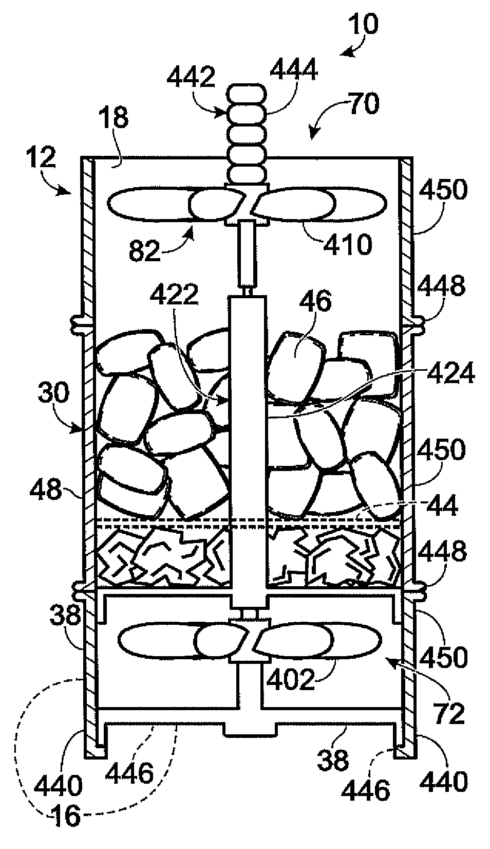
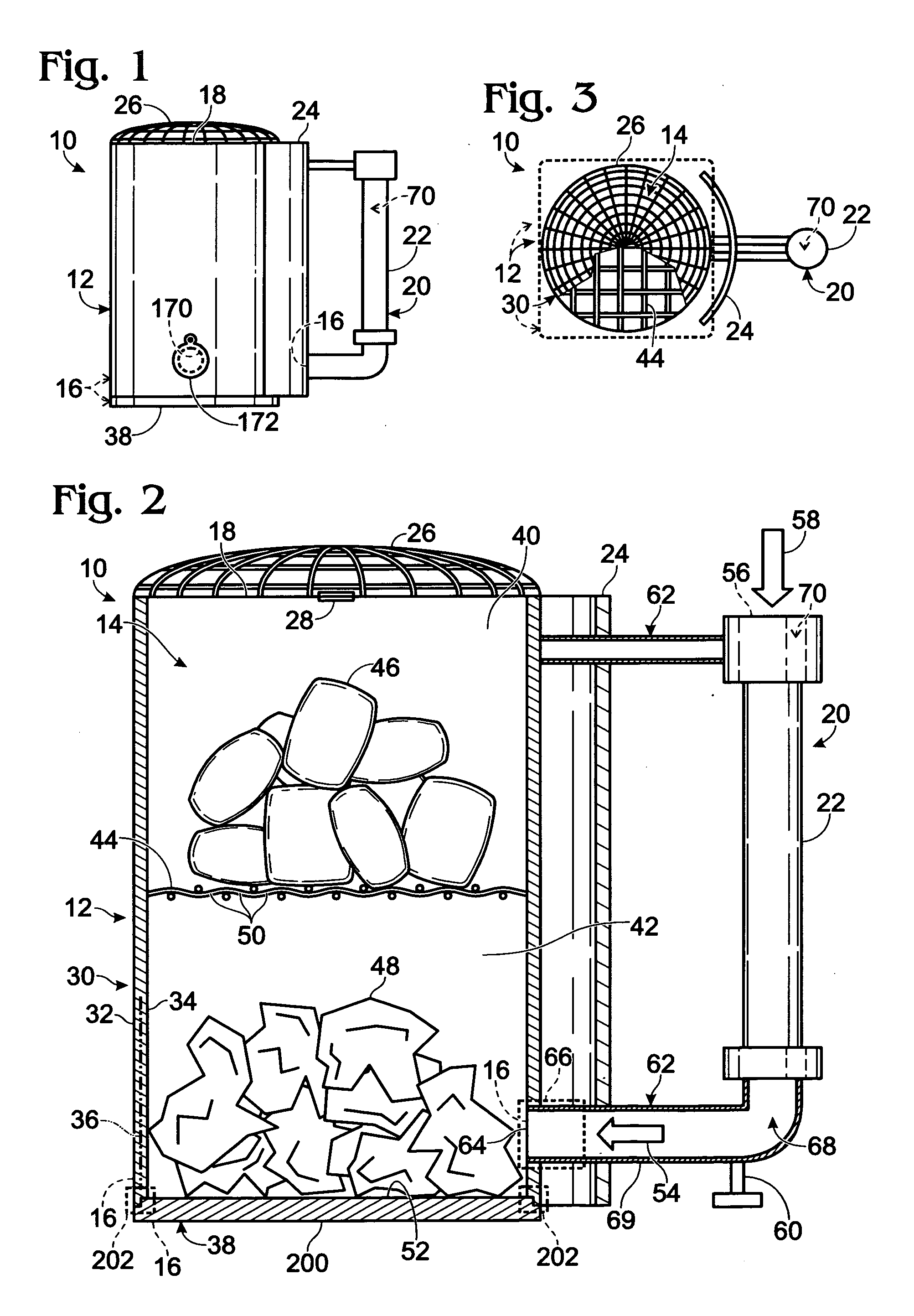
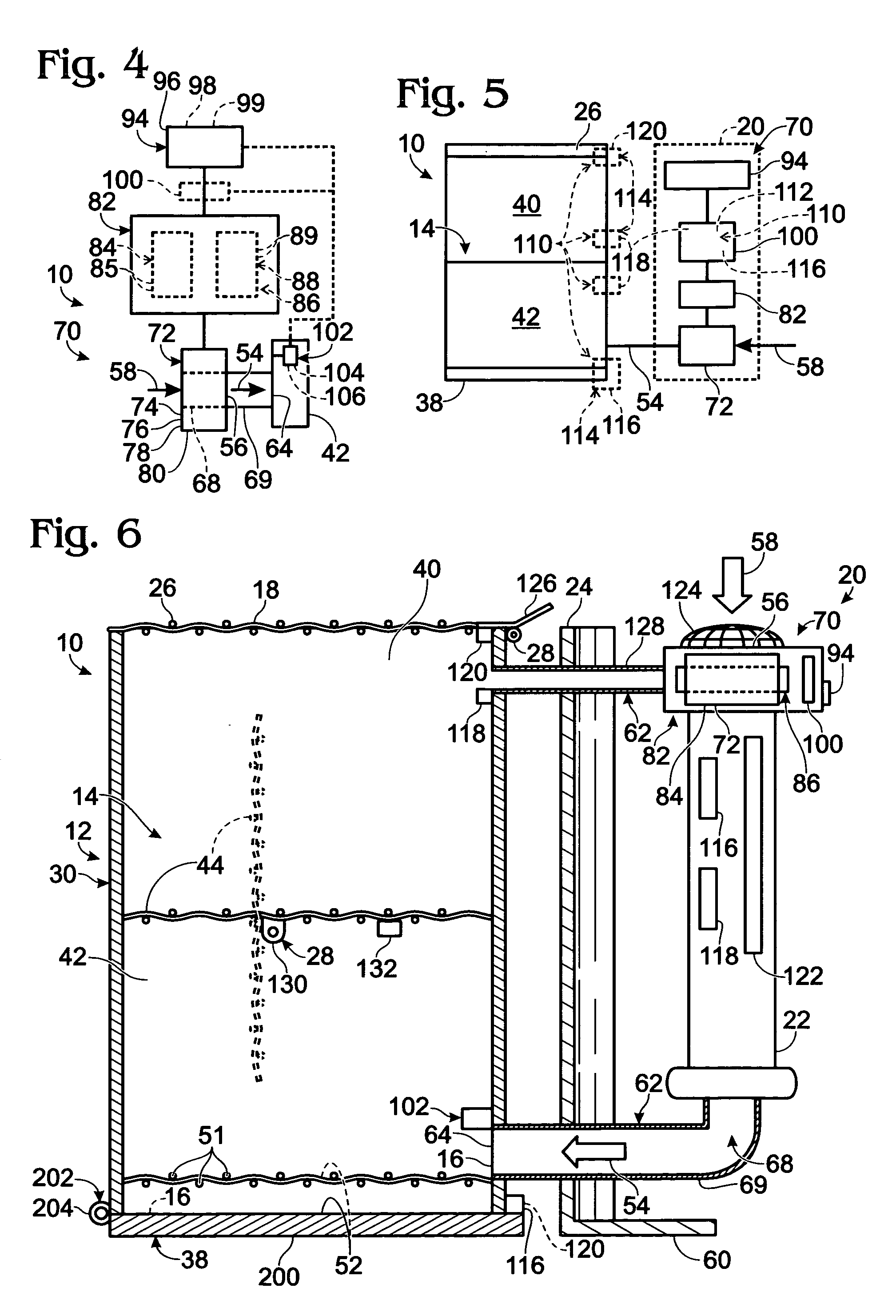
[0032]An illustrative, non-exclusive example of an igniter according to the present disclosure is shown in FIGS. 1 and 2 and generally indicated at 10. Igniter is designed to prepare charcoal, wood, or other combustible fuels for use in barbequing food. Igniter 10 may be referred to herein as a chimney starter or charcoal starter.

[0033]Igniter 10 is designed to “start” charcoal, wood, or a similar barbequing fuel prior to the fuel's use to cook food, typically after removal of the fuel from the igniter and placement of the fuel in a barbeque or similar structure for cooking food. As used herein, “starting” of a barbequing fuel refers to igniting and partially combusting the fuel prior to use of the fuels to barbeque food. As used herein, “barbequing” refers to using partially combusted charcoal, wood, or other coals to cook food, typically via indirect heating and hot gases emitted from the fuel. Barbequing typically occurs in outdoor environments and typically is a slower cooking p...


PUM


Abstract

Devices and methods for accelerating the combustion of non-gas cooking fuels used in barbequing. The devices include a starting fuel for preparing, or starting, a cooking fuel, such as charcoal briquettes, for use to cook food. The starting fuel is contained in a kindling chamber beneath an upper chamber containing the cooking fuel. A powered air delivery mechanism may provide an airflow to the fuels to increase combustion and heating thereof. In some embodiments, the device is a breach-loading device. In some embodiments, the air delivery mechanism is battery-powered. The device may be configured to provide, and / or may be automated to provide, different operating states responsive to the degree of ignition and / or combustion of the fuels in the device. In some embodiments, the device is adapted to automatically be transitioned between forced-air and natural-draft operating states, which may be controlled responsive to sensed operating parameters of the device.

Description

RELATED APPLICATIONS[0001]The present application claims priority to U.S. Provisional Patent Application Ser. No. 60 / 895,682, which was filed on Mar. 19, 2007, and U.S. Provisional Patent Application Ser. No. 60 / 965,093, which was filed on Aug. 16, 2007. The complete disclosures of the above-identified applications are hereby incorporated by reference.FIELD OF THE DISCLOSURE[0002]The present disclosure is directed generally to igniters for use in lighting cooking fuels for barbeques and similar structures, and more particularly to devices which speed or otherwise assist the process of lighting or otherwise preparing these fuels for use to cook food.BACKGROUND OF THE DISCLOSURE[0003]It is a popular activity to cook foods over a charcoal grill, but certain drawbacks to this process have led to the development of various gas fired barbeque products that mimic the effects of charcoal grilling. In general, these devices lack the ability to impart a natural wood smoke flavor to the items ...

Claims


Application Information

Patent Timeline
IPC IPC(8): A47J37/07F24B13/00A47J33/00
CPCA47J37/079F24B1/003F24B1/022F24B1/182Y02A40/928F23Q7/02
Inventor WARNER, JON A.
Owner WARNER JON A
Learn More