Liquid pressure-feed device

a technology of liquid pressure and feed device, which is applied in the direction of domestic cooling apparatus, lighting and heating apparatus, machines/engines, etc., can solve the problems of large number of parts and complicated structure, and achieve the effect of simplifying the structure, and reducing the number of parts

Active Publication Date: 2008-09-18
TLV CO LTD
View PDF4 Cites 4 Cited by
  • Summary
  • Abstract
  • Description
  • Claims
  • Application Information

AI Technical Summary

Benefits of technology

[0004]It is an object of the present invention to provide a liquid pressure-feed device having a reduced number of parts and a simple structure.
[0006]In the liquid pressure-feed device of the present invention, the stopper shaft for restricting the rotational range of the float arm with floating of the float can also serve as the stopper shaft for restricting the rotational range of the sub-arm with descent of the float. Therefore, the liquid pressure feed device of the present invention brings about an excellent effect such that the number of parts decreases and the structure can be simplified.
[0007]In the present invention, as described above, there is provided the stopper shaft supported within the closed vessel, there is formed in the float arm the window through which the stopper shaft extends and which restricts the rotational range of the float arm with floating of the float, and there is formed in the sub-arm the window through which the stopper shaft extends and which restricts the rotational range of the sub-arm with descent of the float. According to this construction, the stopper shaft for restricting the rotational range of the float arm with floating of the float can also serve as the stopper shaft for restricting the rotational range of the sub-arm with descent of the float, and thus it is possible to provide the liquid pressure-feed device having the reduced number of parts and the simple structure.

Problems solved by technology

Thus, there has been the problem that the number of parts is large and the structure is complicated.

Method used


Image

  • Liquid pressure-feed device
  • Liquid pressure-feed device
  • Liquid pressure-feed device

Examples


Embodiment Construction

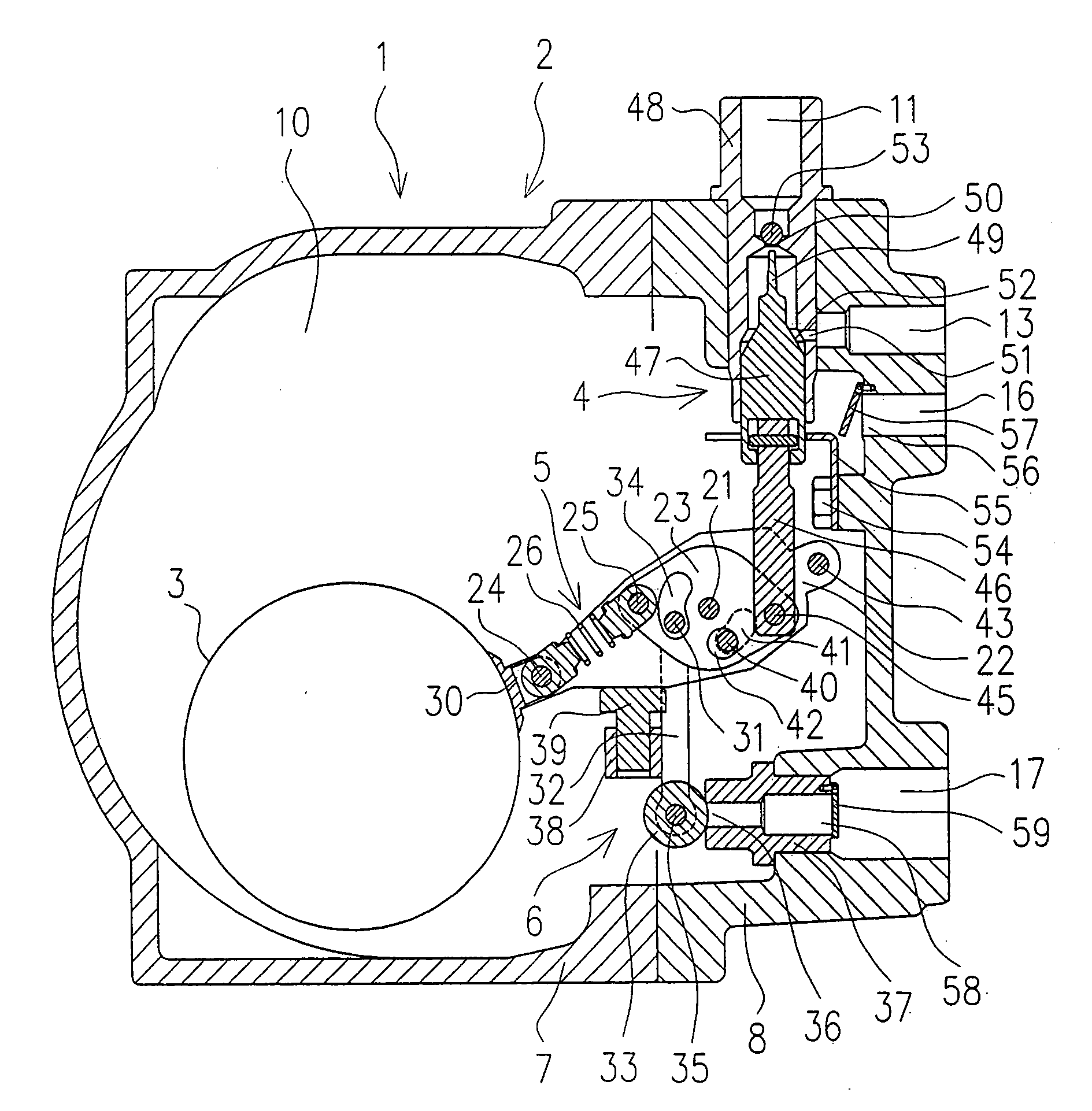
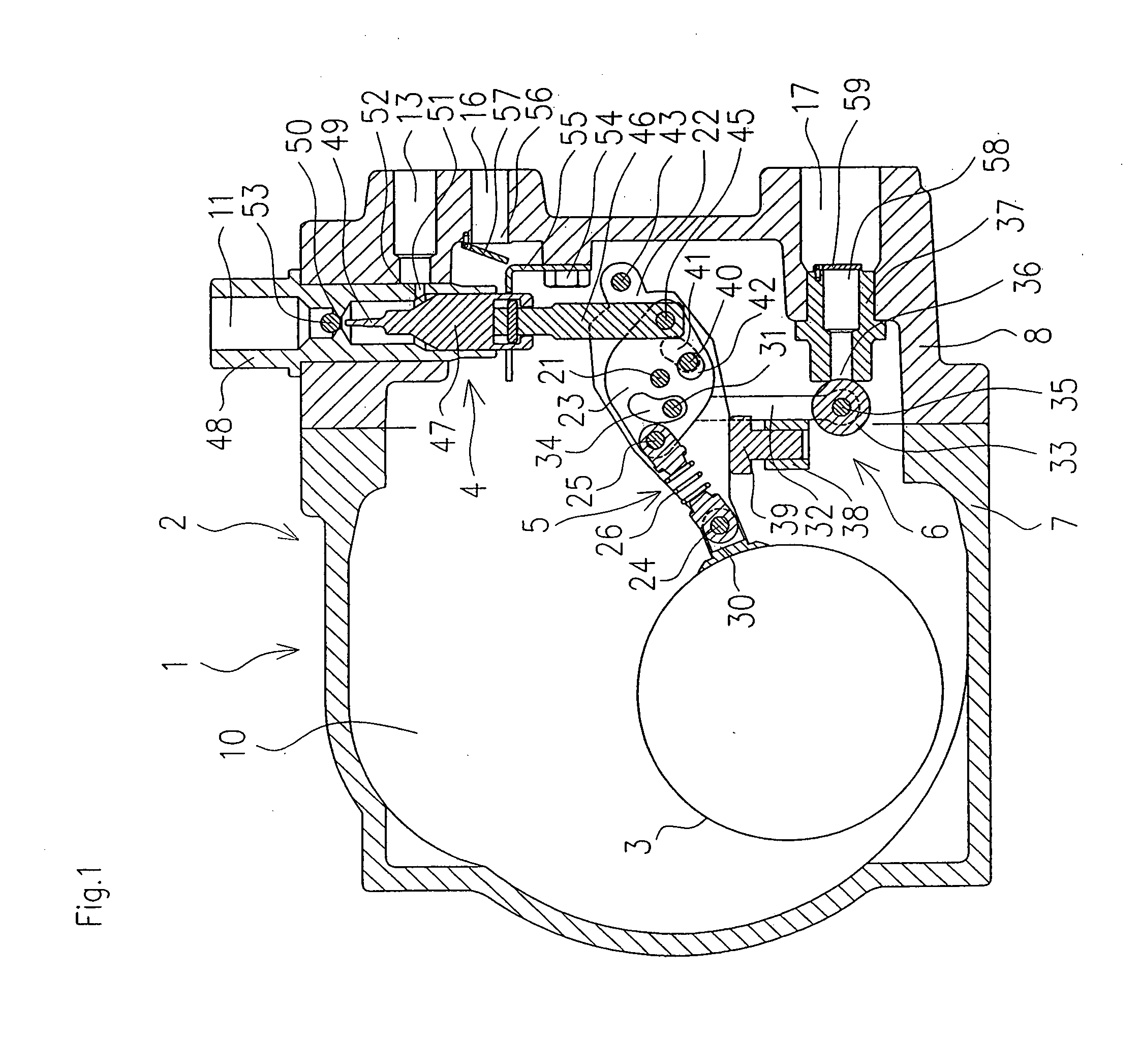
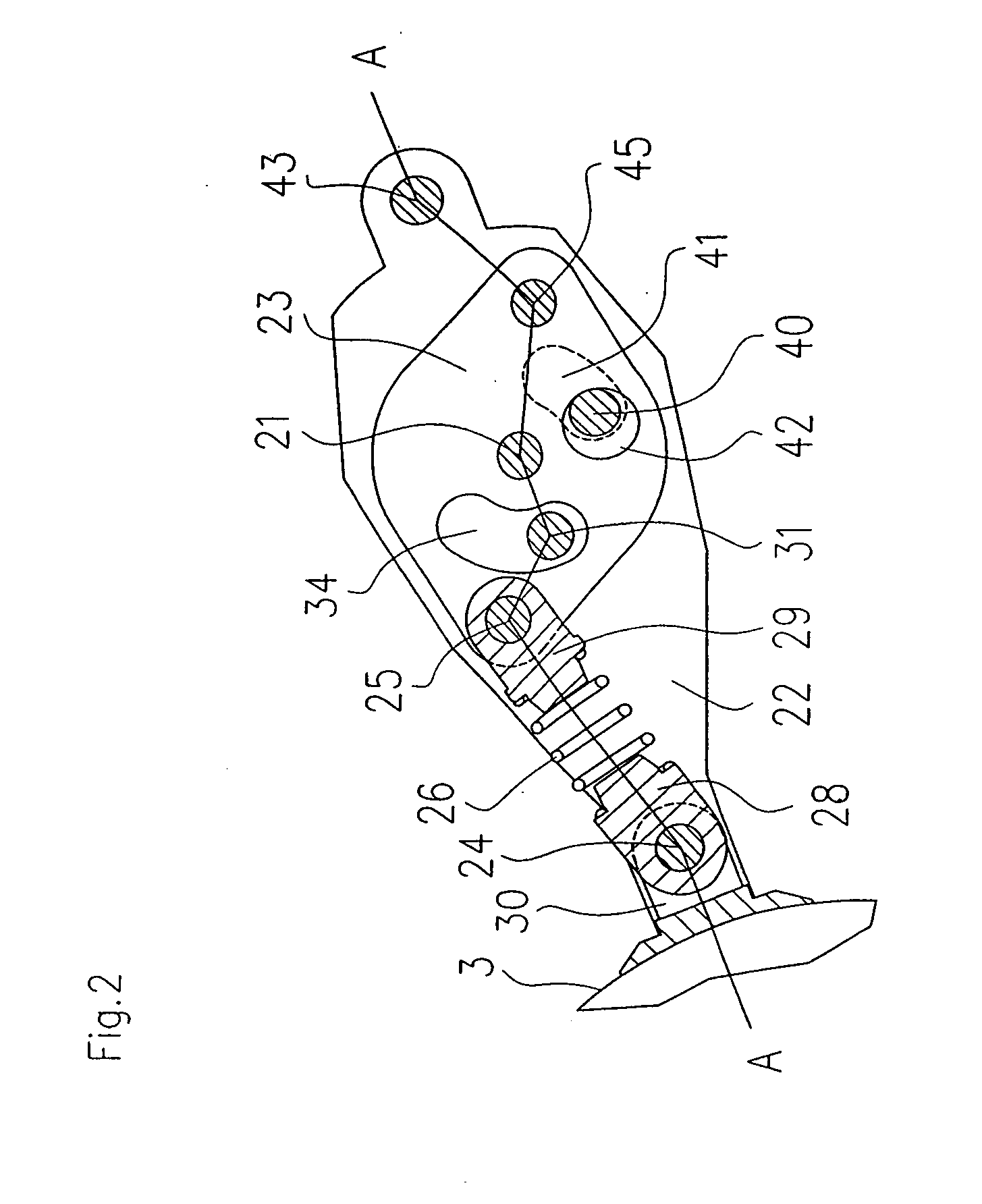
[0013]A description will now be given about an embodiment of the present invention showing a concrete example of the above technical means. FIG. 1 is a sectional view of a liquid pressure-feed device embodying the present invention, FIG. 2 is an enlarged sectional view of a snap mechanism portion shown in FIG. 1 with line A-A inserted therein, FIG. 3 is a sectional view taken on line A-A in FIG. 2, FIG. 4 is an enlarged sectional view of the snap mechanism portion with line B-B inserted therein, and FIG. 5 is a sectional view taken on line B-B in FIG. 4. In a liquid pressure-feed device 1 embodying the present invention, a float 3, a change-over valve 4, a snap mechanism 5 and a liquid discharge valve 6 are disposed within a closed vessel 2. The closed vessel 2 is made up of a body 7 and a lid 8 both joined together with screws (not shown), with a liquid sump space 10 being formed within the vessel. A working fluid inlet port 11, a working fluid discharge port 13, a liquid inlet por...


PUM


Abstract

A liquid pressure-feed device having a reduced number of parts and a simple structure is provided. A snap mechanism has a pivot shaft supported within a closed vessel, a float arm and a sub-arm both adapted to rotate about the pivot shaft, a first shaft supported by the float arm, a second shaft supported by the sub-arm, and a spring mounted between the first and second shafts. A float is connected to the float arm and a change-over valve is connected to the sub-arm through a power transfer shaft. There is provided a stopper shaft supported within the closed vessel, there is formed in the float arm a window through which the stopper shaft extends and which restricts a rotational range of the float arm with floating of the float, and there is formed in the sub-arm a window through which the stopper shaft extends and which restricts a rotational range of the sub-arm with descent of the float.

Description

FIELD OF THE INVENTION[0001]The present invention relates to a liquid pressure-feed device for the feed of liquid such as hot water or fuel under pressure. The liquid pressure-feed device of the present invention is suitable particularly as a device for feeding condensate generated in various steam-using devices to a boiler or a place utilizing waste heat.BACKGROUND OF THE INVENTION[0002]In a conventional liquid pressure-feed device disclosed in Japanese Patent Laid-Open Publication No. Hei 8 (1996)-114175, a working fluid inlet port, a working fluid discharge port, as well as a liquid inlet port and a liquid discharge port are formed in a closed vessel, and a float, a change-over valve and a snap mechanism are installed within the closed vessel. The snap mechanism includes a pivot shaft supported within the closed vessel, a float arm and a sub-arm adapted to rotate about the pivot shaft, a first shaft supported by the float arm, a second shaft supported by the sub-arm, and a spring...

Claims


Application Information

Patent Timeline
Patent Type & Authority Applications(United States)
IPC IPC(8): F04F1/06
CPCF16K31/265
Inventor YUMOTO, HIDEAKI
Owner TLV CO LTD
Why Eureka
Try Eureka