
Air-inflated mattress

a mattress and air technology, applied in the field of air mattresses, can solve the problems that the conventional prior art inflatable mattress cannot compare with the innerspring mattress, and achieve the effects of improving the top surface, increasing the contact area of the mattress, and increasing the comfort of us

Active Publication Date: 2008-09-04
INTEX RECREATION
View PDF44 Cites 15 Cited by
  • Summary
  • Abstract
  • Description
  • Claims
  • Application Information

AI Technical Summary

Benefits of technology

The solution results in a smoother, more comfortable surface and improved edge stability by distributing air pressure evenly and providing additional support, mimicking the performance of an innerspring mattress.

Problems solved by technology

Since the above-mentioned disadvantages exist, the conventional prior art inflatable mattress cannot compare with an innerspring mattress.

Method used


Image

  • Air-inflated mattress
  • Air-inflated mattress
  • Air-inflated mattress

Examples


second embodiment

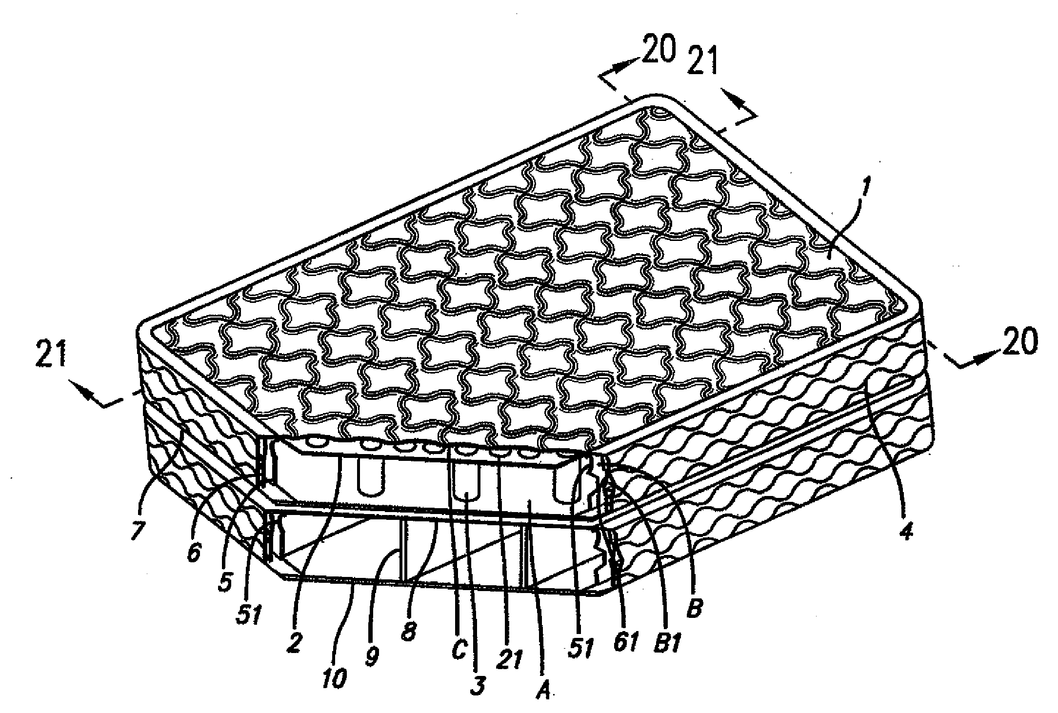
[0057]the invention is described by reference to FIGS. 9, 10, 11 and 11A. As can be seen, there are no vent holes in the tops of anchor separators 3 and there are no riser vent holes in the sides of middle shroud 6. There are only two vent holes 52 and 53, in one side of inner shroud 5, for air to pass from main bladder A into sub-chamber B. In addition, air passes into the space between top layer 1 and middle layer 2 to fill air pockets C by passing around and over the outer edges of middle layer 2, which edges are not welded to top layer 1. Air enters sub-chambers B-1 by gaps at the air inlet. FIG. 11A shows the pattern of side sub-chambers B1 as seen on the surface of outer shroud 4. In this embodiment, the air moves in and out much more slowly than in embodiment one, making it a stiffer mattress.

[0058]A third embodiment of the invention is described by reference to FIGS. 12, 13 and 14 in which middle layer 2 has a plurality of riser vents 54 adjacent to the joint points 56 of an...

fourth embodiment

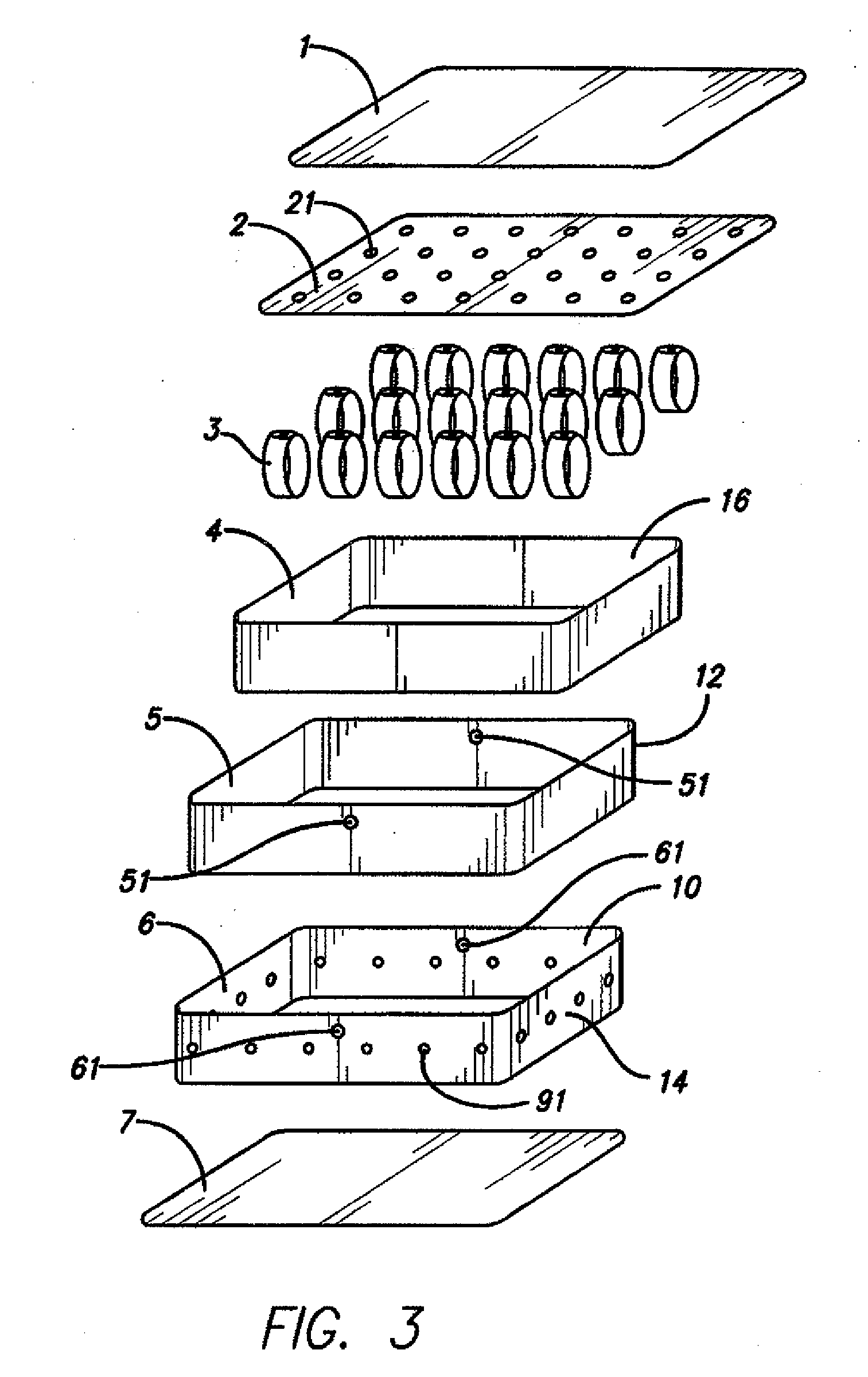
[0060]A fourth embodiment is shown in FIGS. 17 through 21. This embodiment comprises a double mattress, having an upper chamber 70 and a lower chamber 72. Upper chamber 70, shown in FIG. 17, comprises top layer 1, middle layer 2, a plurality of anchor separators 3, an outer shroud 4, an inner shroud 5, a middle shroud 6 and a bottom layer 7. Bottom layer 7 has a plurality of vent holes 41.

[0061]Lower chamber 72, shown in FIG. 18, comprises an upper layer 8, a plurality of I-beam anchor separators 9, an outer shroud 4, an inner shroud 5, a middle shroud 6, and a bottom layer 10. Upper layer 8 has a plurality of vent holes 42 which match up with vent holes 41 in layer 7 of upper chamber 70, so that air may pass between the two chambers, 70 and 72. Layers 7 and 8 are welded together around air vent holes 41 and 42.

[0062]Air passes through vent holes 51 and 61 into sub-chambers B and B1 and into bladder A and through riser vents 21 into small air pockets C. This embodiment provides a hi...


PUM


Abstract

A double air-inflated mattress having an upper chamber and a lower chamber, the upper chamber having a top layer, an outer shroud band, a plurality of anchor separators and a bottom layer, the outer shroud band connecting the top and bottom layers to form an inflatable bladder; a middle layer below said top layer partially sealed to the top layer to form a plurality of sealed or half-sealed cavities, in which some or all of said cavities are in fluid communication with the inflatable bladder, the lower chamber having a top layer, an outer shroud band, a plurality of anchor separators and a bottom layer, said outer shroud band connecting the top and bottom layers to form an inflatable bladder. Each chamber of the double mattress may also have a middle shroud band and an inner shroud band, both of said middle shroud bands being separately welded to the outer shroud bands and the inner shroud bands to form a plurality of closed or half-closed cavities, some or all of said cavities being in fluid communication with its respective inflatable bladder to form a plurality of air pockets on the outer shroud bands of the double air mattress.

Description

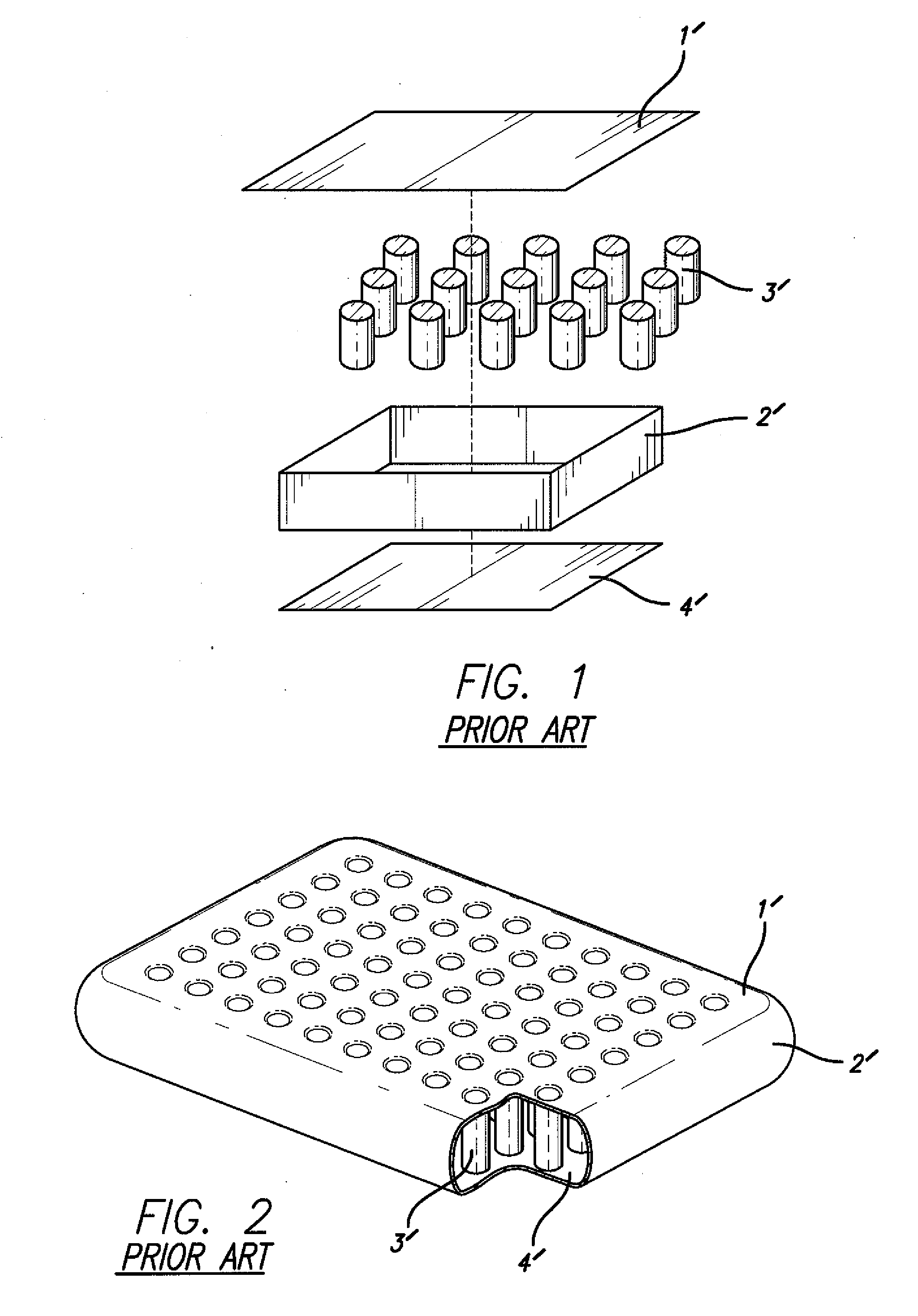
[0001]This application is a divisional of U.S. patent application Ser. No. 11 / 449,287, filed Jun. 8, 2006, now pending.FIELD OF THE INVENTION[0002]The present invention relates to an air-inflated mattress, and more particularly to a supporting structure of an air mattress.DESCRIPTION OF PRIOR ART[0003]The inflatable mattress, by means of its light weight, easy storage and portable features, not only is used as an outdoor apparatus, but also is accepted as indoor furniture. The conventional prior art inflatable mattress, shown in FIGS. 1 & 2, is typically comprised of a top layer 1′, a shroud band 2′, a plurality of cylindrical anchor separators 3′ and a bottom layer 4′, The shroud band 2′ connects the top and bottom layers 1′ and 4′ together to form an inflatable bladder. To keep the bladder level and even, a plurality of cylindrical anchor separators 3′ are respectively connected on the top and bottom layers 1′ and 4′, vertically parallel to the shroud band 2′, thereby keeping the ...

Claims


Application Information

Patent Timeline
Patent Type & Authority Applications(United States)
IPC IPC(8): A47C27/08
CPCA47C27/087A47C27/081
Inventor LIN, HUA HSIANGHSU, YAW YUANLEE, LAN
Owner INTEX RECREATION
Learn More