
Auditory ossicle prosthesis

Active Publication Date: 2008-08-28
HEINZ KURZ MEDIZINTECHN
View PDF13 Cites 11 Cited by
  • Summary
  • Abstract
  • Description
  • Claims
  • Application Information

AI Technical Summary

Benefits of technology

[0013]In this way, without major technical outlay and in a simple way, the advantages of the above-described known auditory ossicle prosthesis of WO 02 / 069850 A1 or of U.S. Pat. No. 6,554,861 B2, which define the generic type, can be made use of, while at the same time neatly avoiding their important disadvantages compared to the prostheses according to documents DE 296 09 687 U1, DE 202 12 771 U1 or EP 0 809 982 B1. As in the “push-on clip with gaps”, which is slightly more complicated and expensive to produce, the modified loop of the first securing element of the auditory ossicle prosthesis according to the invention touches the supply vessels on the auditory ossicle only in the bearing areas. The other vessels run in the areas where the loop does not bear on the auditory ossicle, with the result that the supply of nutrients to the auditory ossicle, for example the long process of the anvil and the lenticular process, is not endangered.
[0014]A particularly preferred embodiment of the auditory ossicle prosthesis according to the invention is distinguished by the fact that the loop is constructed from flat band material and bears flat on the engaged member of the ossicular chain, as a result of which the pressure exerted locally by the securing element on the bone is distributed over a large surface area and in this way can be quite considerably reduced. In this way, it is possible to avoid the formation of constrictions and, therefore, the potential development of local necrosis.
[0016]These disadvantages can be avoided, or at least largely alleviated, in developments of this simple embodiment in which the wire material has a rectangular cross section, and the loop bears with a rectangle surface on the engaged member of the ossicular chain. In this way, as also in the case of the loop made from band material, the surface contact and the pressure exerted on the bone is distributed and locally reduced.
[0027]An embodiment of the device according to the invention is particularly preferred in which the weight distribution of the individual parts of the prosthesis is calculated as a function of a desired, predefinable frequency response of the sound conduction in the middle ear. It is thus possible, without major additional technical outlay, to achieve a degree of tuning of the sound propagation properties by means of an individually configured auditory ossicle prosthesis.
[0028]Such a tuning effect can be achieved, in particular embodiments, by the fact that at least one additional weight is secured on a part of the ossicular chain or of the prosthesis as a function of a desired, predefinable frequency response of the sound conduction in the middle ear.
[0033]A further embodiment of the invention, finally, is distinguished by the fact that the prosthesis is connected to an active vibration part of an active, in particular implantable hearing aid. In this way, further hearing damage can also be largely remedied by application of modern electronics or can at least be substantially alleviated in terms of its effects, in which case, on account of the above-described coating, a physical connection of the prosthesis to the outside world does not cause any problems resulting from increased bacterial ingress into the area of the middle ear, if the coating is made suitably antibacterial.

Problems solved by technology

As a result of this, the sound signal is not transmitted, or is transmitted only incompletely, to the inner ear via the ossicular chain, and this leads to impaired hearing.
With the known auditory ossicle prostheses, the sound conduction between the tympanic membrane and the inner ear is often made possible only to a limited extent, since these prostheses are able only to an extremely limited extent to replace the natural anatomical features of the ossicular chain.
An important problem when fitting an auditory ossicle prosthesis lies in the connection of the prosthesis to a member of the ossicular chain, since this connection should of course on the one hand be secure and permanent, but on the other hand should also be reasonably easy for the operator to establish.
However, special tools are needed to widen the eyelet and to make it easier to push the prosthesis onto the process of the anvil, and also to fix the prosthesis by pressing the slotted eyelet together, which proves quite awkward in practice.
However, in the course of implantation, tilting of the prosthesis could occur, which would make the operation more difficult for the surgeon.
However, the known loop prostheses of the kind described in WO 02 / 0698590 A1 or U.S. Pat. No. 6,554,861 B2 have the considerable disadvantage that they completely enclose the corresponding point of attachment on the auditory ossicle, generally the process of the anvil or the manubrium of the hammer, which in practice can often lead to strangulation of the mucosa lying on the surrounded bone area and, consequently, to necrosis of the structures lying behind this.
Alternatively, however, the loop can also be constructed from wire material, which simplifies production, but can still entail the disadvantages described above.
During this period, scars form and generate unpredictable forces, which can lead to the prosthesis shifting from its local position.
In addition to the post-operative change of position, a further problem also arises after implantation of auditory ossicle prostheses.
Any implantation material introduced into the body, in the context of a reconstruction of the middle ear and of its structures, is therefore subject to a particular stress arising from the fact that it lies in a contaminated and infected environment, which generally attacks the material.
Since the aim of implanting an auditory ossicle prosthesis must be that the implant remains in the patient's middle ear for as long as possible and without complications, a protracted attack of the material can lead to damage of the prosthesis and / or to local infection.
Both consequences are unacceptable.

Method used


Image

  • Auditory ossicle prosthesis
  • Auditory ossicle prosthesis
  • Auditory ossicle prosthesis

Examples


Embodiment Construction

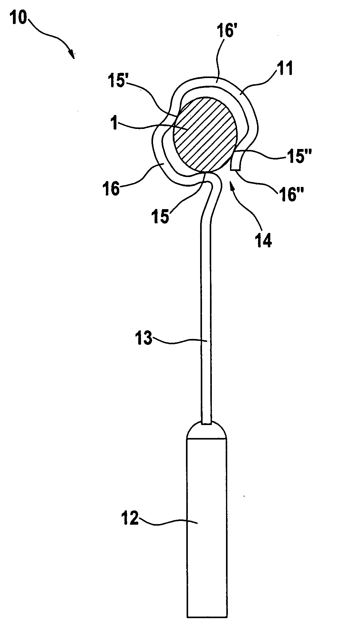
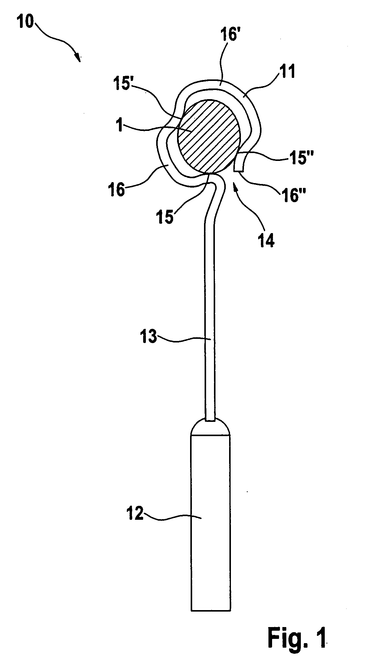
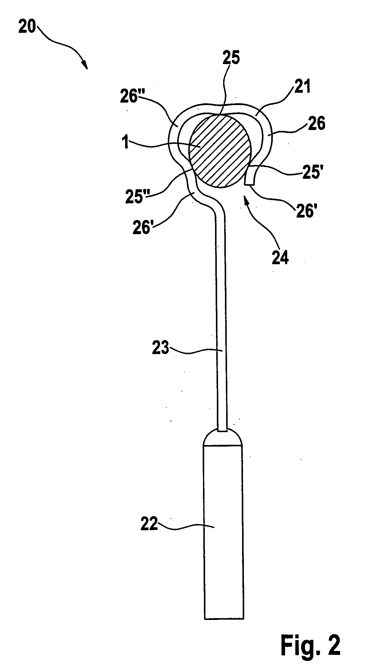
[0039]In all the figures in the drawing, the engaged member of the ossicular chain is designated by reference number 1 and is shown schematically in cross section. In addition, all of the illustrated auditory ossicle prostheses 10; 20; 30 each have, at one of their ends, a first securing element in the form of a loop 11; 21; 31 and, at their opposite ends, a plunger 12; 22; 32. The loop 11; 21; 31 is in each case connected by an elongate shaft 13; 23; 33 to the plunger 12; 22; 32. As has been described above, other embodiments (not shown in the drawing) of the auditory ossicle prosthesis according to the invention can, at their end remote from the loop, have a securing element other than a plunger, for example another loop, a clip, a bell or the like.

[0040]FIG. 1 schematically shows an auditory ossicle prosthesis 10 in which the loop 11, after attachment of the prosthesis 10, bears with a form fit on the engaged member 1 via precisely three areas 15, 15′, 15′′, and, in the circumfer...


PUM


Abstract

An auditory ossicle prosthesis, which at one end has a first securing element for mechanical connection to a member of the ossicular chain, which securing element is designed in the form of a loop that encloses the member, is partially open to the outside via a slit-like aperture and engages with a force fit around the member, the slit-like aperture being considerably smaller than the diameter of the member engaged by the loop, wherein, after attachment, the loop bears with a force fit on the engaged member via at least three areas, and that, in the circumferential direction around the engaged member, at least three areas of the loop do not touch the engaged member but instead each extend at a distance from the surface of the latter. In this way, different geometries and external diameters of the individual points of attachment in the middle ear can be covered with a single auditory ossicle prosthesis and, at the same time, complete strangulation of the point of attachment on the auditory ossicle can be avoided.

Description

FIELD OF THE INVENTION[0001]The invention relates to an auditory ossicle prosthesis which replaces or spans at least one member of the ossicular chain in humans, said auditory ossicle prosthesis having at least at one end a first securing element for mechanical connection to a member of the ossicular chain, in particular to the process of the anvil or to the manubrium of the hammer, which securing element is designed in the form of a loop that encloses the member, is partially open to the outside via a slit-like aperture and engages with a force fit around the member of the ossicular chain to which the mechanical connection is to be established, the slit-like aperture of the loop being considerably smaller than the diameter of the member engaged by the loop.BACKGROUND OF THE INVENTION[0002]An auditory ossicle prosthesis of this kind is, for example, known from German Utility Model DE 296 09 687 U1, from WO 02 / 069850 A1 or from U.S. Pat. No. 6,554,861 B2.[0003]The role of the middle ...

Claims


Application Information

Patent Timeline
IPC IPC(8): A61F2/18
CPCA61F2002/183A61F2/18
Inventor STEINHARDT, UWEHUBER, ALEXEIBER, ALBRECHT
Owner HEINZ KURZ MEDIZINTECHN
Learn More