Turbo-molecular pump and touchdown bearing device

Inactive Publication Date: 2008-08-28
JTEKT CORP
View PDF13 Cites 19 Cited by
  • Summary
  • Abstract
  • Description
  • Claims
  • Application Information

AI Technical Summary

Benefits of technology

[0024]Accordingly, at a touchdown, the rotation speed of the intermediate raceway member with respect to the first raceway member can considerably be reduced to about half the rotation speed of the inner ring with respect to the outer ring in the conventional touchdown bearing. Thus, the first rolling elements can be restrained from being locked to at least one of the first raceway member and the intermediate raceway member. Further, the rotation speed of the third raceway member with respect to the intermediate raceway member can dramatically be reduced to the rotation speed of the inner ring with respect to the outer ring in the conventional touchdown bearing. Thus, the second rolling elements can be restrained from being locked to at least one of the intermediate raceway member and the third raceway member. Consequently, the turbo-molecular pump according to the invention can considerably lengthen the lifetime of the touchdown bearing device, as compared with the conventional turbo-molecular pump.
[0085]Further, the touchdown bearing device according to the invention can considerably lengthen the lifetime, in comparison with the conventional device. Also, the touchdown bearing device according to the invention can dramatically increase the upper limit of the rotation speed of the shaft, at which a touchdown can be caused, as compared with the conventional touchdown bearing device,

Problems solved by technology

In the turbo-molecular pump, vibrations are generated in the rotary shaft when the magnetic bearings are out of control.
Consequently, the conventional turbo-molecular pump has problems that each ball of the bearings is apt to be locked against the associated ring, that seizure of the balls and the rings is liable to occur, and that reduction in the lifetime of the ball bearing is inevitable.

Method used


Image

  • Turbo-molecular pump and touchdown bearing device
  • Turbo-molecular pump and touchdown bearing device
  • Turbo-molecular pump and touchdown bearing device

Examples


first embodiment

[0094]FIG. 1 is a cross-sectional view taken in an axial direction of a turbo-molecular pump according to the invention.

[0095]This turbo-molecular pump includes a turbo-molecular pump body 1 and a controller (not shown) and is communicated with vacuum equipment (not shown).

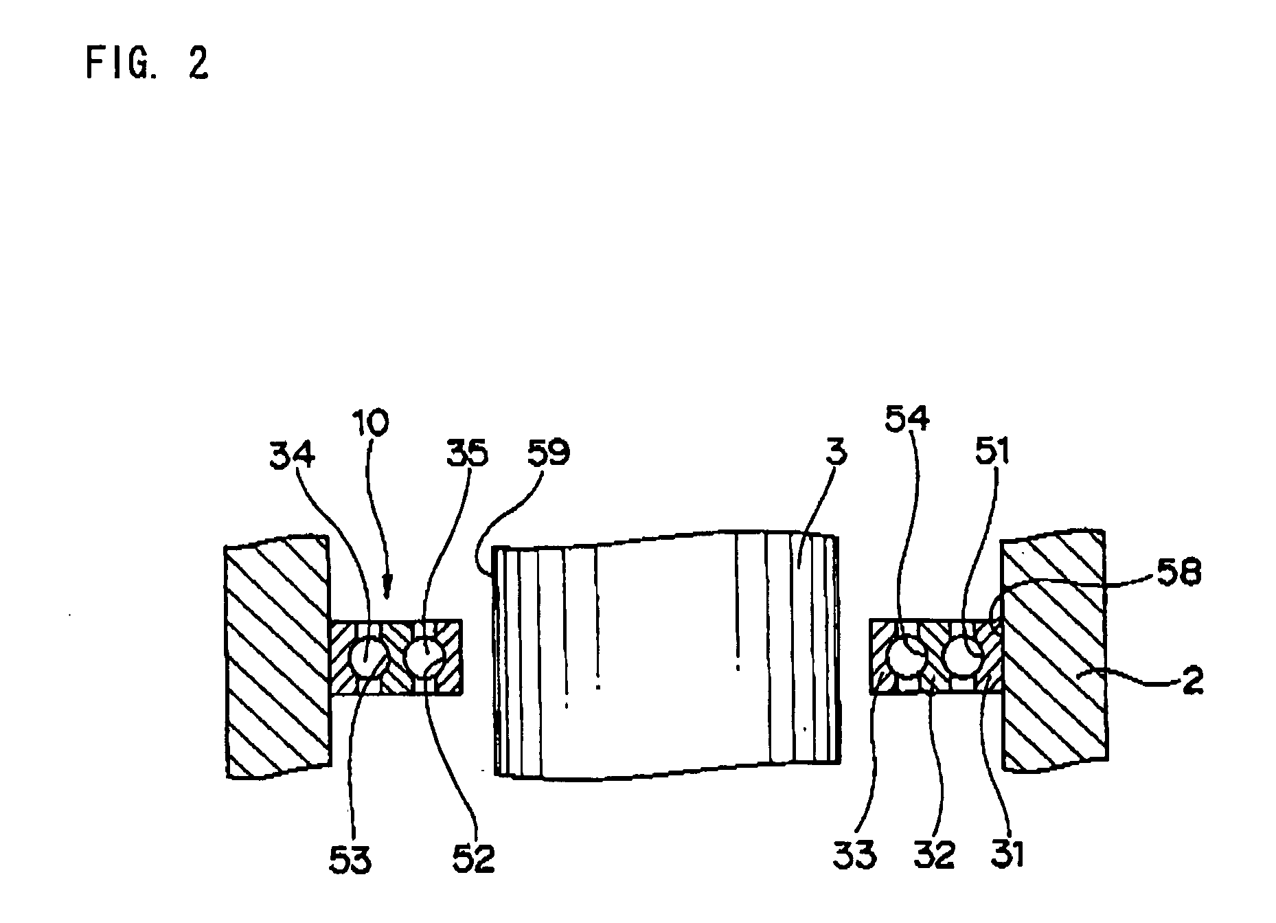
[0096]The turbo-molecular pump body I includes a housing 2, a rotary shaft 3 serving as the shaft, a motor 4 that drives the rotary shaft 3, an axial position detecting sensor 16, radial position detecting sensors 14 and 15, an axial magnetic bearing 6, first and second radial magnetic bearings 7 and 8, and first and second touchdown bearing devices 10 and 11 according to the first embodiment of the invention.

[0097]The axial position detecting sensor 16 detects the axial position of the rotary shaft 3 and outputs a signal representing the axial position of the rotary shaft 3 to the controller. Further, the radial position detecting sensors 14 and 15 are disposed in the axial direction of the rotary shaft 3 by bein...

second embodiment

[0141]FIG. 4 is a partially schematic cross-sectional view illustrating a turbo-molecular pump according to a second embodiment of the invention.

[0142]This turbo-molecular pump includes a housing 302, a rotary shaft 303, and a touchdown bearing device 310 according to the second embodiment of the invention.

[0143]The turbo-molecular pump according to the second embodiment differs from the turbo-molecular pump 10 according to the first embodiment, in which the touchdown bearing device 10 according to the invention is interposed between the inner peripheral cylindrical surface 58 and the outer peripheral surface 59 of the rotary shaft 3, in that the touchdown bearing device 310 according to the invention is interposed between an inner peripheral surface 318 of a cylindrical portion, which constitutes a part of the rotary shaft 303, and an outer peripheral cylindrical surface 319 of a cylindrical portion 317 of the housing 302, which is positioned radially and inwardly from the inner pe...

third embodiment

[0149]FIG. 5 is a partially schematic cross-sectional view illustrating a turbo-molecular pump according to a third embodiment of the invention.

[0150]In the following description of the turbo-molecular pump according to the third embodiment, the description of operations, advantages, and modifications common to the first and third embodiments is omitted. Only operations, advantages, and modifications of the third embodiment, which differ from those of the first embodiment, are described below.

[0151]The first touchdown bearing device 10 includes a deep groove type first full complement ball bearing 130, and a deep groove type second full complement ball bearing 150. The first full complement ball bearing 130 includes the first inner ring 131 serving as the first raceway member, the first outer ring 132 serving as the second raceway member, and a plurality of first balls 133 serving as the first rolling elements, whereas the second full complement ball bearing 150 includes the second ...


PUM


Abstract

A touchdown bearing device includes an outer ring fixed to a housing, an inner ring radially opposed to the outer ring, an intermediate ring radially interposed between the outer ring and the inner ring, a first ball interposed between the outer ring and the intermediate ring, and a second ball interposed between the intermediate ring and the inner ring. The touchdown bearing device is configured so that when a magnetic bearing normally operate, a rotary shaft and the inner ring are brought into a noncontact state, and that meanwhile, when the magnetic bearing does not normally operate, the rotary shaft is supported by the inner ring so as to support the rotary shaft against the housing.

Description

BACKGROUND OF THE INVENTION[0001]The present invention relates to a turbo-molecular pump, and to a touchdown bearing device for use in a turbomolecular pump and a vacuum pump.[0002]A conventional turbo-molecular pump is described in JP-A-2004-116558.[0003]This turbo-molecular pump has a rotary shaft, a housing, magnetic bearings, and ball bearings serving as touchdown bearings. The magnetic bearings have electromagnets and magnetically support the rotary shaft in a non-contact manner during a normal operation.[0004]On the other hand, each of the ball bearings has an inner ring, an outer ring and balls. The outer ring is internally fit into the inner peripheral surface of the housing, while the inner ring is noncontact with the rotary shaft when the magnetic bearings normally operate.[0005]The ball bearings are configured so that when an error (human error) in operation of controlling the magnetic bearing or an electrical power failure causes the magnetic bearings not to normally ope...

Claims


Application Information

Patent Timeline
IPC IPC(8): F04B17/00F16C32/04F16C33/58F16C33/32
CPCF04D19/042F04D29/058F04D29/059F16C2360/45F16C32/0442F16C32/0489F16C39/02F16C19/55
Inventor OKUDA, KOUICHIHIGASHIMOTO, OSAMU
Owner JTEKT CORP
Why Eureka
Try Eureka