
Method and apparatus for determining deterioration of secondary battery, and power supply system therewith

a secondary battery and deterioration technology, applied in the direction of material analysis, instruments, transportation and packaging, etc., can solve the problems of inability to measure the voltage stabilized battery, significant errors in the estimation of the soc obtained, and the methods described above are lack of accuracy, so as to accurately and correctly determine the soh, accurately and accurately determine the deterioration level or the discharge capability of the battery, and high accuracy

Active Publication Date: 2008-08-28
FURUKAWA ELECTRIC CO LTD
View PDF16 Cites 88 Cited by
  • Summary
  • Abstract
  • Description
  • Claims
  • Application Information

AI Technical Summary

Benefits of technology

[0028]One object of the present invention is to provide a method and apparatus for detecting SOC and SOH of a storage battery capable of performing an optimum management by detecting both the SOC and the SOH accurately at the same level. Another object of the present invention is to provide a method for determining SOH of a secondary battery capable of determining the SOH of the secondary battery with high accuracy by accurately correcting a change of internal impedance or internal resistance due to the operating temperature of the secondary battery. Still another object of the present invention is to provide a method for estimating a deterioration level or a discharge capability of a battery, by estimating am impedance at a reference direct current value, with the influence of the impedance due to a charge current and a discharge current that is superimposed in normal operation being eliminated.Means for Solving the Problems
[0076]Besides, since the relational expression between the superimposed direct current IDC and the impedance Z, which is required for obtaining the impedance Zb at the reference direct current IDCb value based on the impedance Za and the DC component IDCa at the time of measurement, includes at least one exponential term of the direct current IDC, it becomes possible to determine the deterioration level or the discharge capability of the battery with higher accuracy.

Problems solved by technology

In this method, it is not possible to measure a stabilized battery voltage because the battery voltage is greatly affected by the over-voltage due to charge or discharge.
Accordingly, the stabilized battery voltage can not be obtained, resulting in generation of significant errors in estimation of the SOC obtained from the linearity.
The methods described above are lack of accuracy, because the methods utilize the measured raw data for the estimation and there is no consideration of, for example, a state of health (SOH).
However, the battery capacity of the storage battery is lowered and decreased from its initial capacity in accordance with the deterioration of the storage battery, thus the accuracy of the calculated SOC becomes lower than that of the initial stage associated with the deterioration.
These methods also use only the SOC at the time when measured to determine an SOC and thus lack the accuracy of the determination.
Any of the methods use only an SOH at the time when measured without consideration of factors, like temperature or other and thus lack the accuracy of the determination of an SOH.
Accordingly, even if the internal impedance or internal resistance falls within the allowable range at normal temperature, they may be out of the allowable range at lower temperature, and thus it may not be able to use the secondary battery under the lower temperature.
The internal impedance or internal resistance of the secondary battery has a complicated temperature characteristic, so it is difficult to make an accurate approximation with a simple approximate formula, and it has been difficult to make temperature correction for the internal impedance or internal resistance with high accuracy.

Method used


Image

  • Method and apparatus for determining deterioration of secondary battery, and power supply system therewith
  • Method and apparatus for determining deterioration of secondary battery, and power supply system therewith
  • Method and apparatus for determining deterioration of secondary battery, and power supply system therewith

Examples


first embodiment

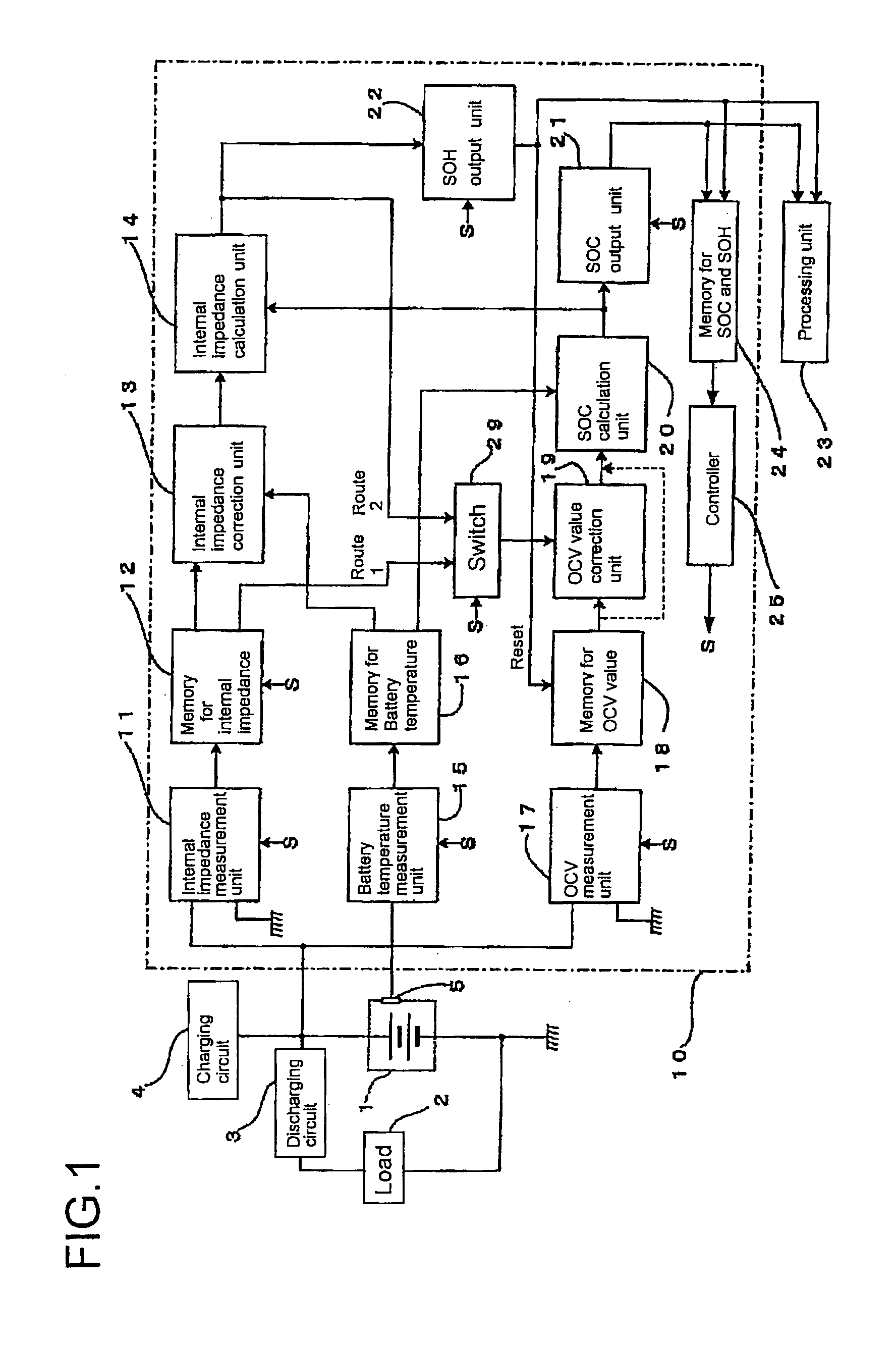
[0146]FIG. 1 is a block diagram illustrating an apparatus for detecting an SOH and an SOC of a storage battery according to the first embodiment of the present invention.

[0147]In FIG. 1, connected to a storage battery 1 is a discharging circuit 3 controlling a current supplied from the storage battery 1 to a load 2, a charging circuit 4 for supplying a charge power, and an SOH and SOC detection unit 10 for measuring SOH and SOC at open circuit.

[0148]The SOH and SOC detection unit 10 has an internal impedance measurement unit 11, a memory 12 for internal impedance, an internal impedance correction unit 13, a battery temperature measurement unit 15, a memory 16 for battery temperature, an open circuit voltage (OCV) measurement unit 17, a memory 18 for OCV value, an OCV value correction unit 19, a state of charge (SOC) calculation unit 20, and an internal impedance calculation unit 14. The internal impedance measurement unit 11 is connected to a positive electrode and a negative electr...

second embodiment

[0182]FIG. 8 is a block diagram illustrating a configuration of an apparatus for detecting SOH and SOC of a storage battery related to the second embodiment of the present invention. In FIG. 8, the same parts as in FIG. 1 are designated by the same symbols.

[0183]In FIG. 8, the storage battery 1 is connected to the load 2 via the discharging circuit 3 and further connected to the charging circuit 4 and an SOH and SOC detection unit 30. Connected between the charging circuit 4 and the storage battery is a first ammeter 6. Connected between the load 2 and the storage battery 1 is a second ammeter 7.

[0184]The SOH and SOC detection unit 30, as the same as shown in the above mentioned embodiment, has the internal impedance measurement unit 11, the memory 12 for internal impedance, the internal impedance correction unit 13, the battery temperature measurement unit 15, the memory 16 for battery temperature, the switch 29, the SOC output unit 21, and the SOH output unit 22.

[0185]Further, the...

third embodiment

[0202]Next, a method and an apparatus for detecting deterioration of a secondary battery and a power supply system therewith according to a preferable embodiment of the present invention will be explained in detail with reference to drawings.

[0203]Hereinafter, there will be explained an embodiment in the case where the present invention is applied to a power supply unit for vehicles and power supply system for vehicles having a function of determining a deterioration of a secondary battery mounted on a vehicle and the like.

[0204]FIG. 11 is a block diagram illustrating the configuration of a power supply unit according to the third embodiment of the present invention. In FIG. 11, a power supply unit 211 for vehicles includes a secondary battery 212, a current sensor 213 for measuring a current of the secondary battery 212, a voltage sensor 214 for measuring a voltage of the secondary battery, and a temperature sensor 215 for measuring a temperature of the secondary battery 212. The u...


PUM

PropertyMeasurementUnit
frequencyaaaaaaaaaa
frequencyaaaaaaaaaa
currentaaaaaaaaaa

Abstract

A method for detecting SOC and SOH of a storage battery includes: calculating an SOC value of the storage battery with use of an SOC calculation unit based on a measured voltage value or a measured current value of the storage battery and calculating an SOH value of the storage battery with use of an SOH calculation unit based on the SOC value; further calculating a new SOC value with use of the SOC calculation unit based on the SOH value and calculating a new SOH value with use of the SOH calculation unit based on the new SOC value, these further calculations of SOC value and SOH value being repeated a prescribed n times of at least one so as to obtain an nth calculated SOC value and an nth calculated SOH value; outputting the nth calculated SOH value as an SOH output value and outputting the nth calculated SOH value as an SOC output value; and storing the SOH output value into a memory.

Description

TECHNICAL FIELD[0001]The present invention relates to a method for determining a state of health (SOH) of a secondary battery supplying power to a load. More particularly, the present invention relates to a method for determining the SOH of a secondary battery based on an estimation result of an internal impedance or an internal resistance of the secondary battery.BACKGROUND ART[0002]As a method for detecting a state of charge (SOC) of a storage battery, for example, as described in Japanese Unexamined Patent Application Publication No, 2004-530880, there is a method for estimating SOC by measuring the battery voltage with using the relation (linearity) between a battery voltage and SOC.[0003]In this method, it is not possible to measure a stabilized battery voltage because the battery voltage is greatly affected by the over-voltage due to charge or discharge. Particularly, in the vehicle, the storage battery supplies a power to each load during and after engine start and is charged...

Claims


Application Information

Patent Timeline
Patent Type & Authority Applications(United States)
IPC IPC(8): G01N27/416
CPCG01R31/3624G01R31/3679G01R31/3662G01R31/389G01R31/3842G01R31/392
Inventor IWANE, NORIYASUKIMURA, ATSUSHIFUJIMURA, KOJIWATANABE, YUICHISATO, TOSHIYUKIIWAHANA, FUMIKAZUILJIMA, TAKASHI
Owner FURUKAWA ELECTRIC CO LTD
Learn More