
Location positioning method in handover between networks

a technology of location positioning and network, applied in the field of location information system, can solve the problem that the service based on the related art supl architecture cannot properly process an area event, and achieve the effect of efficient performing an area even

Active Publication Date: 2008-08-21
LG ELECTRONICS INC
View PDF4 Cites 53 Cited by
  • Summary
  • Abstract
  • Description
  • Claims
  • Application Information

AI Technical Summary

Benefits of technology

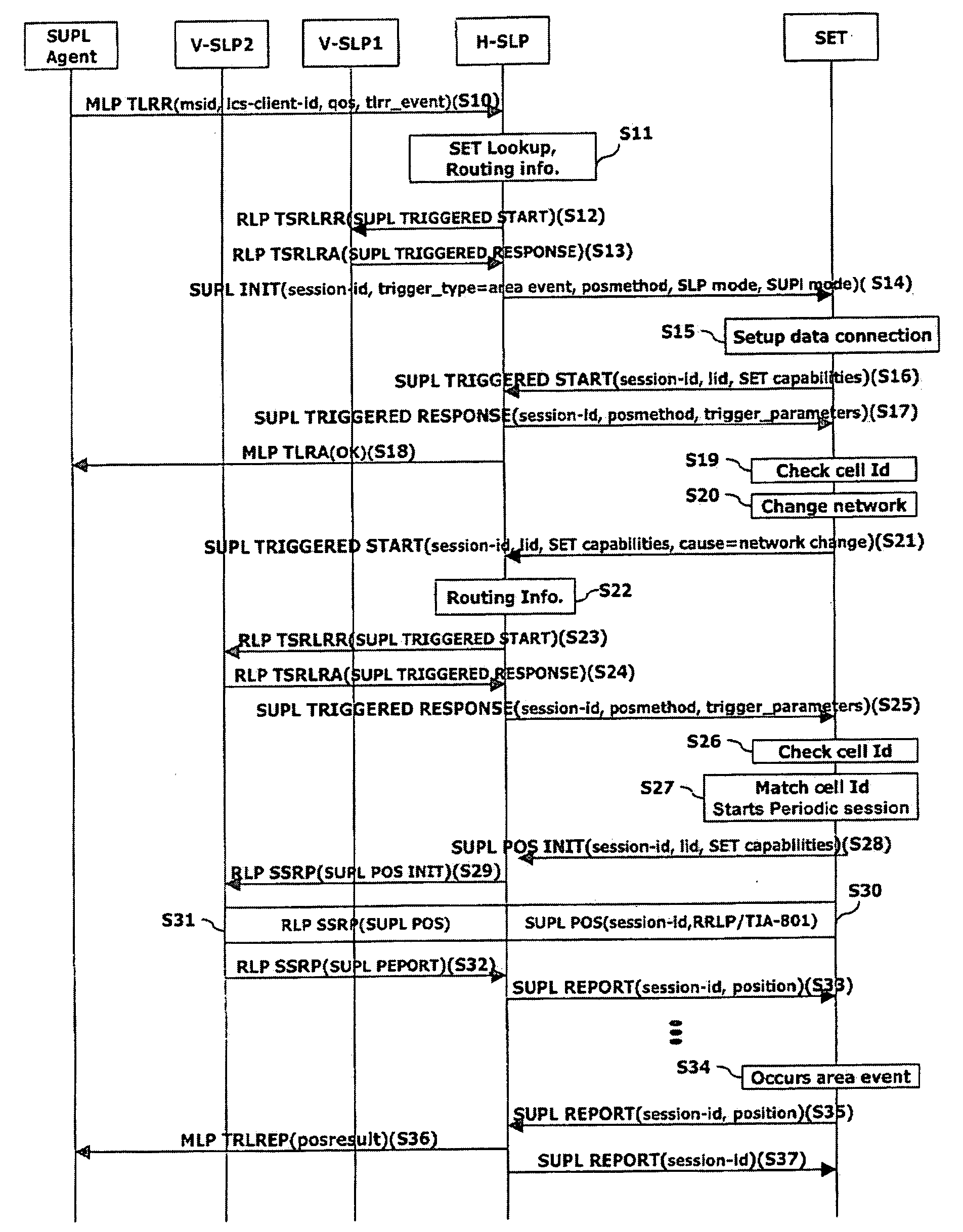
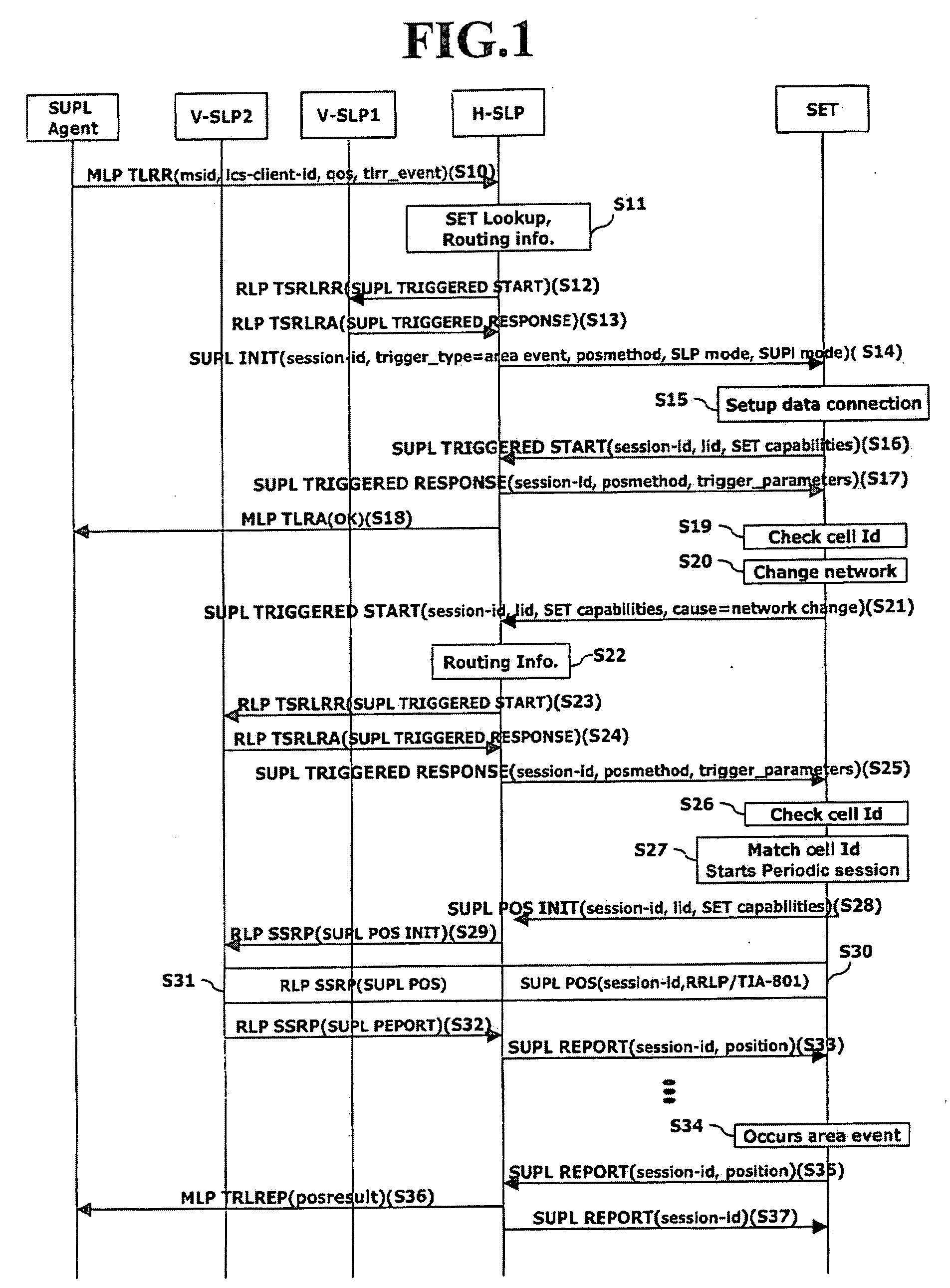
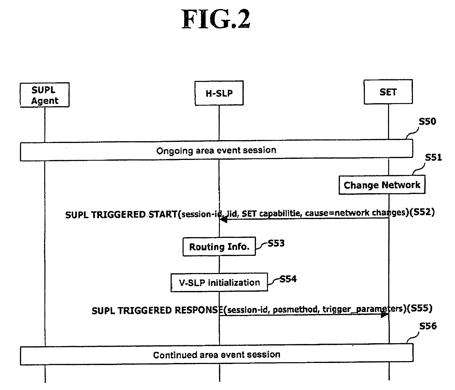
[0013]Therefore, an object of the present invention is to provide a location positioning method for efficiently performing an area event even when a registered network is changed in a triggered location service based upon a Secure User Plane Location (SUPL) architecture.

Problems solved by technology

However, the triggered location service based upon the related art SUPL architecture cannot properly process an area event when an initially registered network is changed.

Method used


Image

  • Location positioning method in handover between networks
  • Location positioning method in handover between networks
  • Location positioning method in handover between networks

Examples


second embodiment

[0069]FIG. 3 illustrates a Network initiated Proxy mode, as the location positioning method in handover between networks according to the present invention. In particular, FIG. 3 shows the case that V-SLP determines whether a terminal is within coverage area of a serving network or not, and then informs the terminal about the determined result.

[0070]As described in FIG. 3, while a trigger session such as a periodic or an area event session is ongoing, SET transmits a SUPL POS INIT message to H-SLP so as to start a positioning session with V-SLP (S60). Preferably, in case area-id (e.g. cell-id) is used to detect an area event, SET sends the SUPL POS INIT message to H-SLP when an MNC or an SID is changed.

[0071]Upon receiving the SUPL POS INIT message, H-SLP forwards the SUPL POS INIT message to a V-SLP1 using an RLP message (S62). V-SLP1 compares lid included in the SUPL POS INIT message with coverage area of V-SLP1 itself, and then checks whether SET is within its coverage area or no...

third embodiment

[0080]FIG. 4 illustrates a Network initiated Non-Proxy mode, as the location positioning method in handover between networks according to the present invention.

[0081]As shown in FIG. 4, while a trigger session such as a periodic or an area event session is ongoing, SET transmits a SUPL POS INIT message to start a positioning session with a V-SPC1 of V-SLP1 (S80). In case area-id (e.g. cell-id) is used to detect an area event, SET transmits the SUPL POS INIT message to V-SPC1 when an MNC or an SID is changed (S81).

[0082]Upon receiving the SUPL POS INIT message, V-SPC1 compares lid included in the SUPL POS INIT message with coverage area of V-SPC1 itself, and checks whether SET is within its coverage area. If the checked result shows that SET is within its coverage area, V-SPC1 proceeds to the step (S90), which will be explained later, and then continues to perform the periodic or the area event session. If not, V-SPC1 transmits a SUPL END message including the checked result (no cove...


PUM


Abstract

Disclosed is a location information system based upon a SUPL (Secure User Plane Location) architecture, and more particularly, to a location positioning method and terminal based on an area event in handover between networks. The method according to one embodiment includes: if a network is changed or if a terminal is outside of the coverage area of a serving network while an area event is ongoing, requesting, by the terminal, new event trigger parameters to a home network through a first message; determining, by the home network, a serving network of the terminal by using location identifier included in the first message; receiving, the home network, the location identifier of a target area for which the positioning is requested from the determined serving network; and transmitting, the home network, the new event trigger parameters including the area identifier to the terminal through a second message.

Description

[0001]This present application is a continuation of co-pending U.S. patent application Ser. No. 11 / 727,132 filed on Mar. 23, 2007 for which priority is claimed under 35 U.S.C. §120, the entire contents of which are hereby incorporated by reference. This nonprovisional application claims priority under 35 U.S.C. § 119(e) on U.S. Provisional Application No(s). 60 / 785,280 and 60 / 872,508 filed on Mar. 24, 2006 and Dec. 4, 2006, respectively. This Nonprovisional application also claims priority under 35 U.S.C. § 119(a) on Korean Patent Application No. 10-2007-0017598 filed on Feb. 21, 2007.BACKGROUND OF THE INVENTION[0002]1. Field of the Invention[0003]The present invention relates to a location information system based upon a Secure User Plane Location (SUPL) architecture, and more particularly, to a triggered location positioning method based on an area event in handover between networks.[0004]2. Description of the Related Art[0005]A mobile communication system provides a location serv...

Claims


Application Information

Patent Timeline
Patent Type & Authority Applications(United States)
IPC IPC(8): H04Q7/20H04W4/02H04W4/20H04W8/12H04W36/14H04W60/04H04W64/00
CPCH04W4/02H04W4/20H04L67/18H04W60/04H04W64/00H04W36/14H04L67/52H04W36/24H04W4/029
Inventor SHIM, DONG-HI
Owner LG ELECTRONICS INC
Learn More