
Joint Materials and Configurations

a technology of configuration and joint space, applied in the direction of joint tightening/covering, engine sealing, construction, etc., can solve the problems of difficult, if not impossible, to cut joint spaces adjacent to fenestrations or other wall penetrations, difficult to cut joint spaces on vertical surfaces or from scaffolding, and high cos

Inactive Publication Date: 2008-08-21
TROUT JOHN T
View PDF32 Cites 6 Cited by
  • Summary
  • Abstract
  • Description
  • Claims
  • Application Information

AI Technical Summary

Benefits of technology

[0020]In some embodiments, both the first component and the second component have a top surface, a bottom surface, a first side, a second side, a portion of the top surface of the...

Problems solved by technology

There are numerous disadvantages to cutting joint spaces in preparation for receiving a sealant.
For example, in applications involving walls, it is difficult, if not impossible, to cut joint spaces adjacent to fenestrations or other wall penetrations in order to seal them to the surrounding material without damaging the frame or finish of the penetrating fixture in the cutting process.
In addition, the cutting of joint spaces is expensive and difficult to do on vertical surfaces or from scaffolding.
Furthermore, dust resulting from the cutting process may settle in the formed joint space.
The dust may hinder sealant adhesion.
However, processes using forms and other standoff devices are also known to include drawbacks.
For example, because standoffs are typically constructed of fairly rigid material that are put in place prior to the application of plastic construction materials, the forms often cannot be readily removed from the resulting joint space between the cured material without the destructive use of power tools or other equipment.
Often time standoffs are simply left in place within the joint space, however, because the standoff is made of rigid material that does not fill a substantial portion of the space, the standoff will not provide an insulating effect.
Moreover, a standoff left in place may prevent the joint from opening and closing as intended, and may potentially lead to damage of the adjoining materials.
A punctured foam backer rod may emit gas which will cause bubbling in the plastic sealant.
Another drawback to the use of backer rod is that it may be inserted at an inconsistent depth within the joint space.
If this occurs, the joint sealant may fail prematurely because it was not placed at the desired depth-to-width ratio.
In addition, expensive sealants may be wasted because the joint space is filled to a greater depth than desired.

Method used


Image

  • Joint Materials and Configurations
  • Joint Materials and Configurations
  • Joint Materials and Configurations

Examples


Embodiment Construction

[0048]While this invention may be embodied in many different forms, there are described in detail herein specific preferred embodiments of the invention. This description is an exemplification of the principles of the invention and is not intended to limit the invention to the particular embodiments illustrated.

[0049]For the purposes of this disclosure, like reference numerals in the figures shall refer to like features unless otherwise indicated.

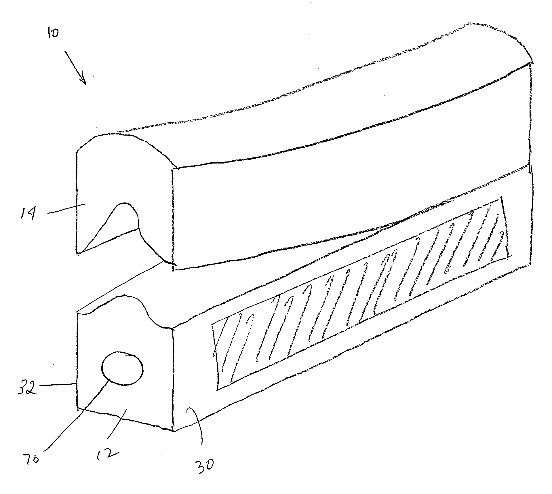
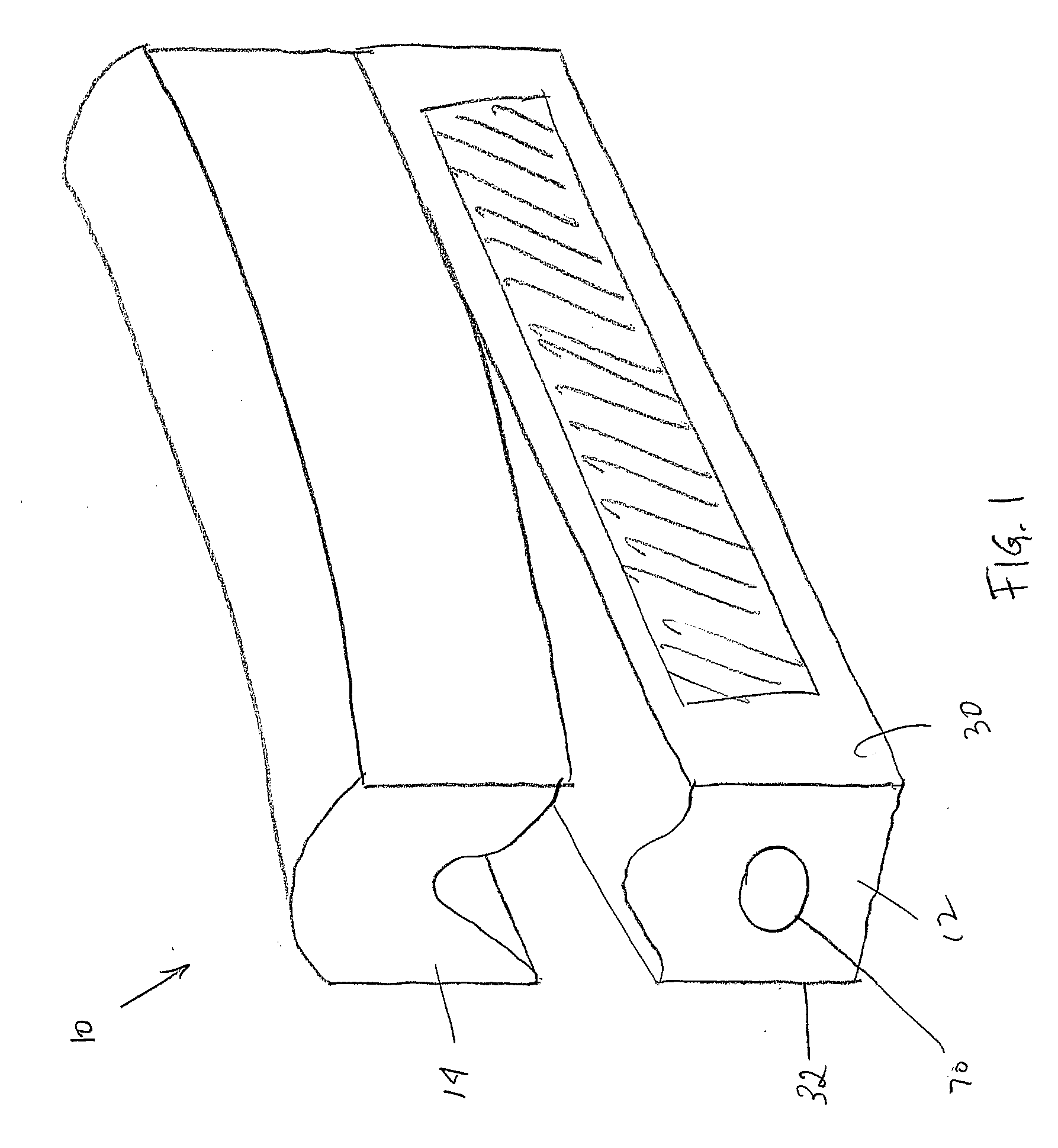
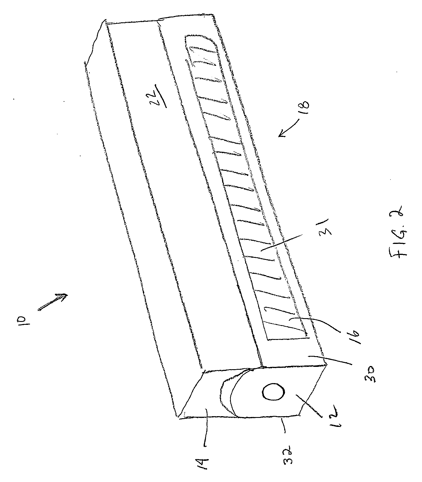
[0050]As indicated above, the present invention is directed to a variety of embodiments. A first embodiment is depicted in FIG. 1, wherein a joint spacer is shown generally at 10. The joint spacer 10 is comprised of a first component 12, a second component 14, and an adhesive 16.

[0051]The joint spacer 10 has a first state shown generally at 18, as depicted in FIG. 2, and a second state, shown generally at 20, as depicted in FIG. 3. Referring now to FIG. 2, the joint spacer 10, in the first state, is a single or unitary structure 22. That is...


PUM


Abstract

A method and apparatus for forming a sealed joint between first and second construction surfaces comprises a joint spacer having a first state and a second state. In the first state, the joint spacer has a unitary structure which includes a first component and a second component, wherein in the first state the second component is engaged to the first component. In the second state the second component is disengaged from the first component. The joint spacer also has an adhesive disposed on at least a portion of only the first component, the adhesive configured to adhere to the first construction surface.

Description

CROSS-REFERENCE TO RELATED APPLICATIONS[0001]Not ApplicableSTATEMENT REGARDING FEDERALLY SPONSORED RESEARCH[0002]Not ApplicableBACKGROUND OF THE INVENTION[0003]1. Field of the Invention[0004]Various embodiments of the present invention are directed to systems for maintaining and / or at least partially filling a space between two materials, particularly materials such as concrete, brick, stucco, plastic, wood, metal, and other somewhat rigid materials associated with construction and manufacturing. In some embodiments the invention is directed to joints, such as expansion joints, and more specifically to backings, fillers, forms, stand-offs, spacers and other devices suitable for insertion into the space between materials to form a joint, hereinafter referred to cumulatively as a spacer or joint spacer. In those embodiments directed to a joint spacer, the spacer comprises one or more components that are configured for placement into and / or removal from a joint space.[0005]2. Descripti...

Claims


Application Information

Patent Timeline
IPC IPC(8): F16J15/02
CPCE04B1/6813E06B2001/628E06B1/62E04B1/6816
Inventor TROUT, JOHN T.
Owner TROUT JOHN T
Learn More