Digital hold in a phase-locked loop
a phase-locked loop and digital hold technology, applied in the direction of generating/distributing signals, pulse techniques, instruments, etc., can solve the problems of not meeting the clock signal generated in holdover mode may still drift, and certain plls may fail to meet the requirements of holdover
- Summary
- Abstract
- Description
- Claims
- Application Information
AI Technical Summary
Problems solved by technology
Method used
Image
Examples
Embodiment Construction
)
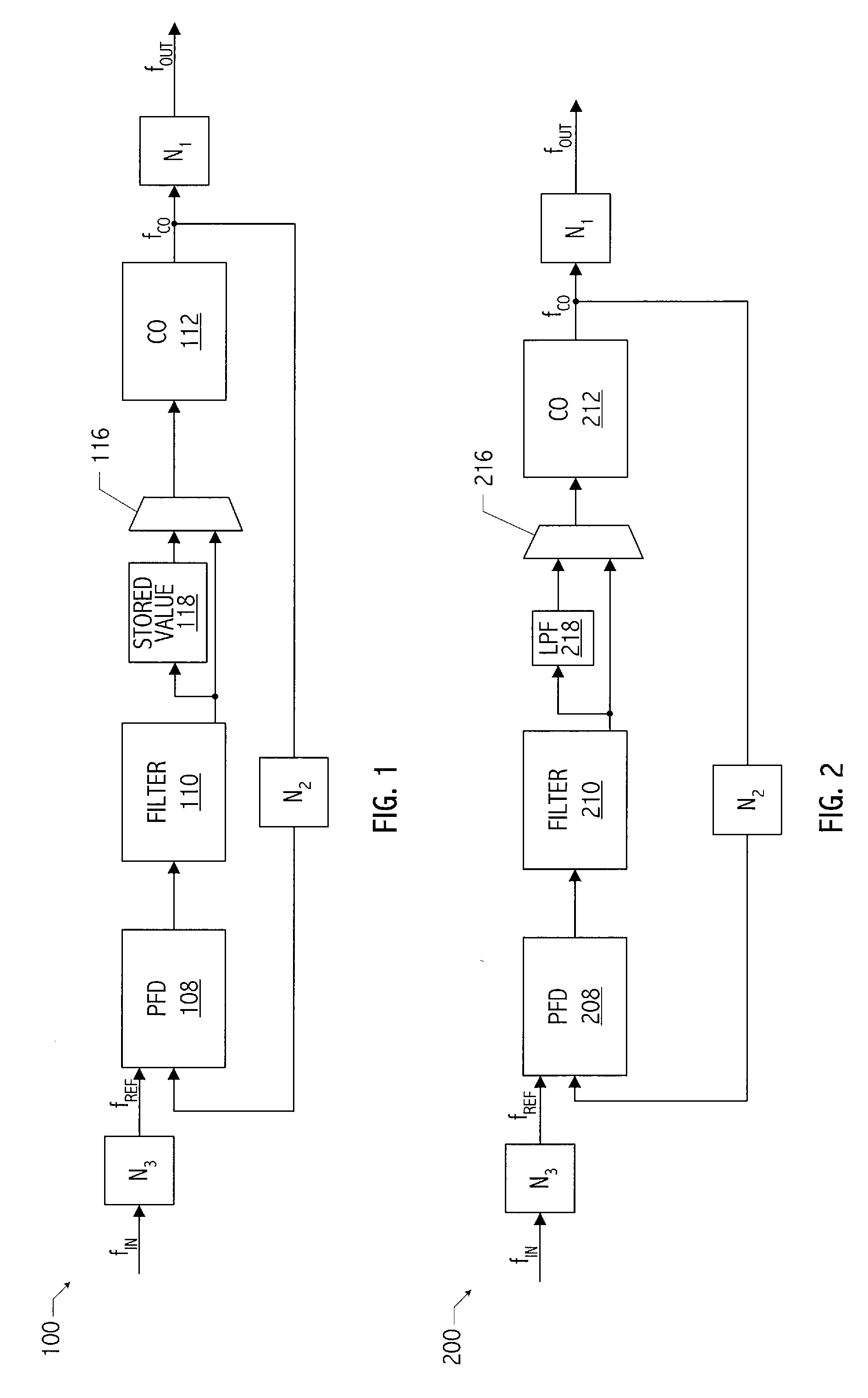
[0020]Referring to FIG. 1, an exemplary phase-locked loop (i.e., PLL 100) architecture has a programmable bandwidth (i.e., f3 dB) and a programmable reference frequency (i.e., fREF). Such features of a PLL architecture are described in provisional application No. 60 / 827,530, filed Sep. 29, 2006, entitled “Hitless Switching Architecture,” naming Srisai R. Seethamraju, Ronald B. Hulfachor, and Shailesh Chitnis as inventors, which application is incorporated herein by reference. Note that features of PLL 100 are exemplary only and the invention disclosed herein may be implemented in other PLL architectures.
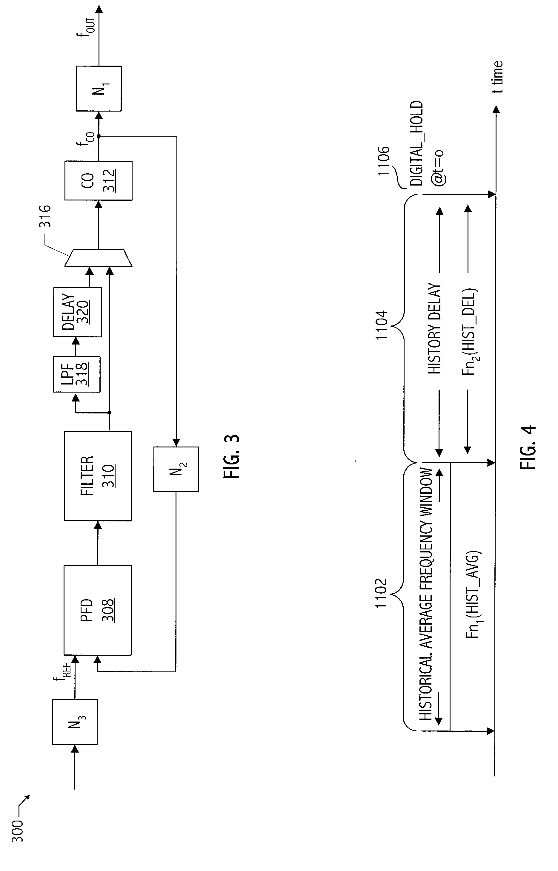
[0021]When a holdover condition occurs in PLL 100, that is, when reference clock signal fREF fails, which may be indicated by a loss of signal condition indicator, loop filter 110 of PLL 100 is “frozen” such that a digital control value used to drive controllable oscillator 112 no longer tracks changes to the reference signal, and the frozen output of the loop filter (e.g., stored v...
PUM
 Abstract
Description
Claims
Application Information
 - Generate Ideas
- Intellectual Property
- Life Sciences
- Materials
- Tech Scout
- Unparalleled Data Quality
- Higher Quality Content
- 60% Fewer Hallucinations
Browse by: Latest US Patents, China's latest patents, Technical Efficacy Thesaurus, Application Domain, Technology Topic, Popular Technical Reports.
© 2025 PatSnap. All rights reserved.Legal|Privacy policy|Modern Slavery Act Transparency Statement|Sitemap|About US| Contact US: help@patsnap.com


