
Distributed object-oriented appliance control system

a control system and object-oriented technology, applied in the field of distributed object-oriented appliance control system, can solve the problems of difficult design, development, testing, diagnosis, control, and debugging of basic appliance models

Inactive Publication Date: 2008-08-07
WHIRLPOOL CORP
View PDF19 Cites 134 Cited by
  • Summary
  • Abstract
  • Description
  • Claims
  • Application Information

AI Technical Summary

Benefits of technology

[0011]The the software architecture implementations

Problems solved by technology

The basic appliance models typically are difficult to design, develop, test, diagnose, control, and debug due to the diversity of componentry and the associated diversity of implementation choices.

Method used


Image

  • Distributed object-oriented appliance control system
  • Distributed object-oriented appliance control system
  • Distributed object-oriented appliance control system

Examples


second embodiment

[0501]At least the smart coupler 1042 can hold a routing table constructed from a plurality of discovery confirmation messages. In one embodiment, the routing table holds identifiers from other nodes with each identifiers routing information. In a second embodiment, the routing table holds identifiers from other nodes with each identifier's routing information and with a new identifier that will be used to represent the identifiers from other nodes. The new identifier can be considered a proxy identifier.

third embodiment

[0502]In a third embodiment, the routing table can have software function pointers linking the arbitrary software component to the functional identifiers and associated routing information instead of proxy identifiers. As stated previously, nodes can have the same functionality as couplers. This embodiment is an exemplary embodiment where the routing table is coupling an arbitrary software component to another arbitrary software component or to a routing table held by a coupler, or to second arbitrary software component on another node.

[0503]In addition to the six collaboration examples, a seventh collaboration example includes first and second arbitrary software components comprised within the application logic 59 where both the first and second arbitrary software components have identifiers and can be identified within the structures 74, which can comprise the routing table. In this collaboration, the first arbitrary software component sends a message to the second arbitrary softw...


PUM


Abstract

The invention relates to an object-oriented control system for an appliance, configurable by a configuration mechanism in selective operable communication with a plurality of object oriented control systems using a packet protocol for constructing messages comprising identifiers from a plurality of namespaces associated with the building blocks of object-oriented systems. The meaning of each unique identifier within class library namespace is uniquely meaningful throughout a universe of appliances.

Description

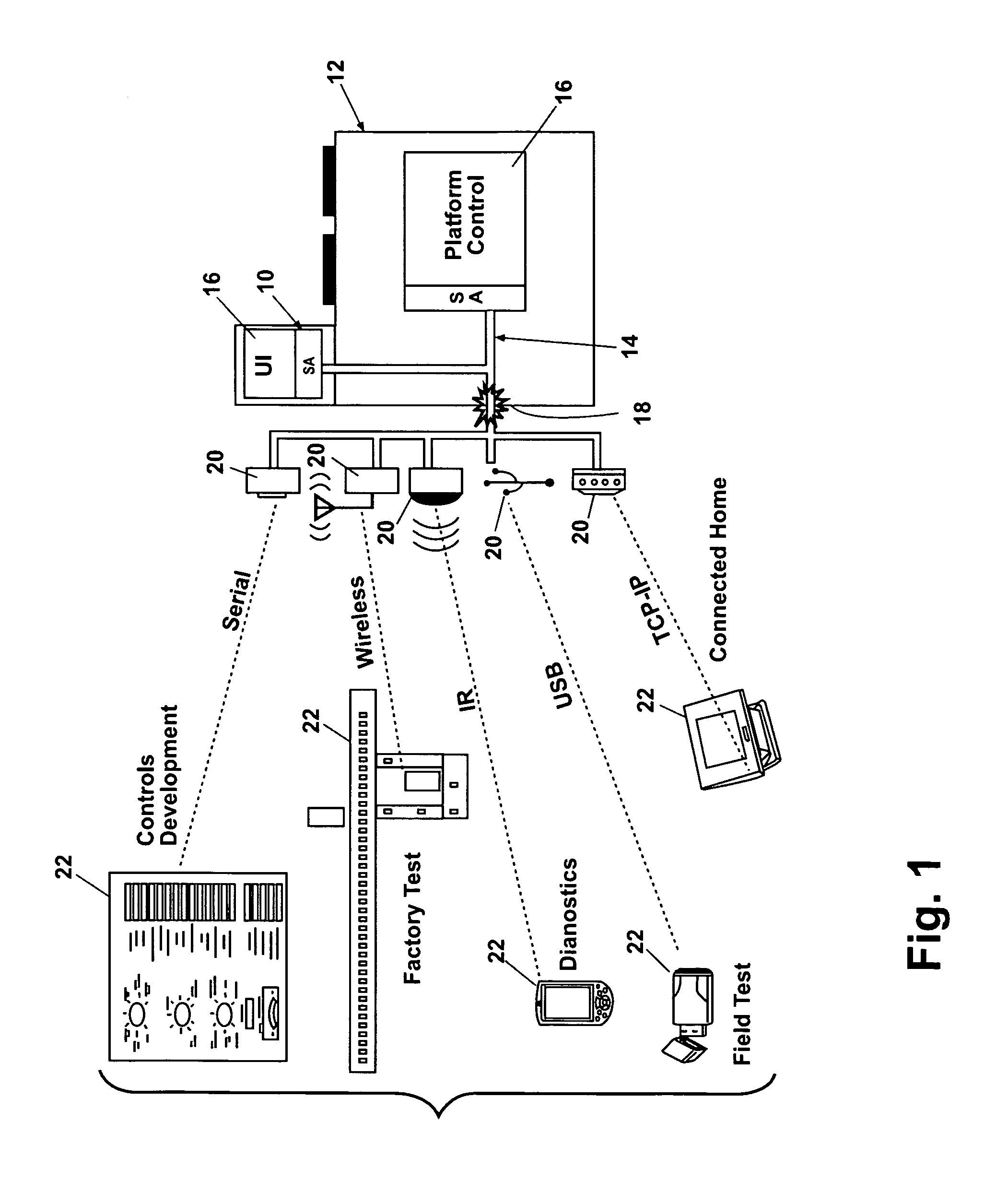
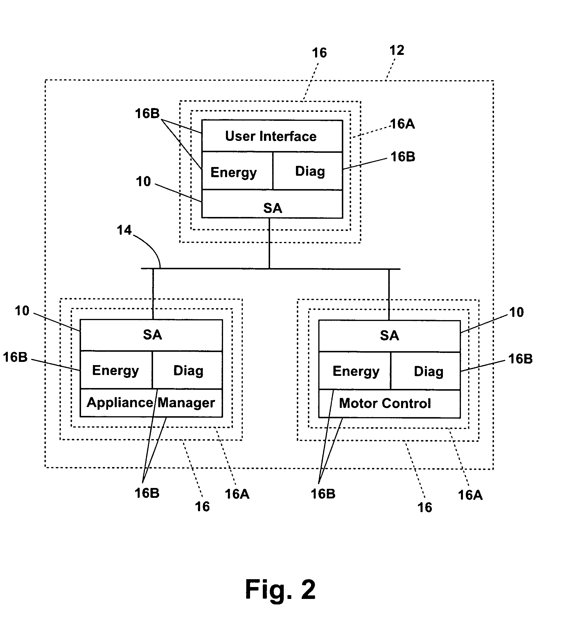
CROSS-REFERENCE TO RELATED APPLICATIONS[0001]This application is a continuation-in-part of International Application No. PCT / US2006 / 022420, filed Jun. 8, 2006 and International Application No. PCT / US2006 / 022503, filed Jun. 9, 2006, both of which claim the benefit of U.S. Provisional Patent Application No. 60 / 595,148, filed Jun. 9, 2005, all of which are incorporated in there entireties by reference.BACKGROUND OF THE INVENTION[0002]1. Field of the Invention[0003]The invention relates to network systems of appliances and the software architecture of the network.[0004]2. Description of the Related Art[0005]Household appliances are typically comprised of one or more components which cause the electromechanical, electrothermal, and electrochemical operations of the appliance. For example, an oven may include an appliance management component, having a printed circuit board (PCB) with memory thereon, as well as a user interface component, such as a control panel or keypad for a user to is...

Claims


Application Information

Patent Timeline
IPC IPC(8): G06F17/00
CPCG06F9/54G06F11/3495H04L12/2803H04L12/2807H04L12/2818H04L12/282H04L67/12H04L12/2827H04L12/2832H04L2012/285H05B6/688H04L69/26H04L12/2825
Inventor MCCOY, RICHARD A.
Owner WHIRLPOOL CORP
Learn More