
Device and procedure for axial thrust compensation

Inactive Publication Date: 2008-08-07
RITZ PUMPENFAB
View PDF4 Cites 11 Cited by
  • Summary
  • Abstract
  • Description
  • Claims
  • Application Information

AI Technical Summary

Benefits of technology

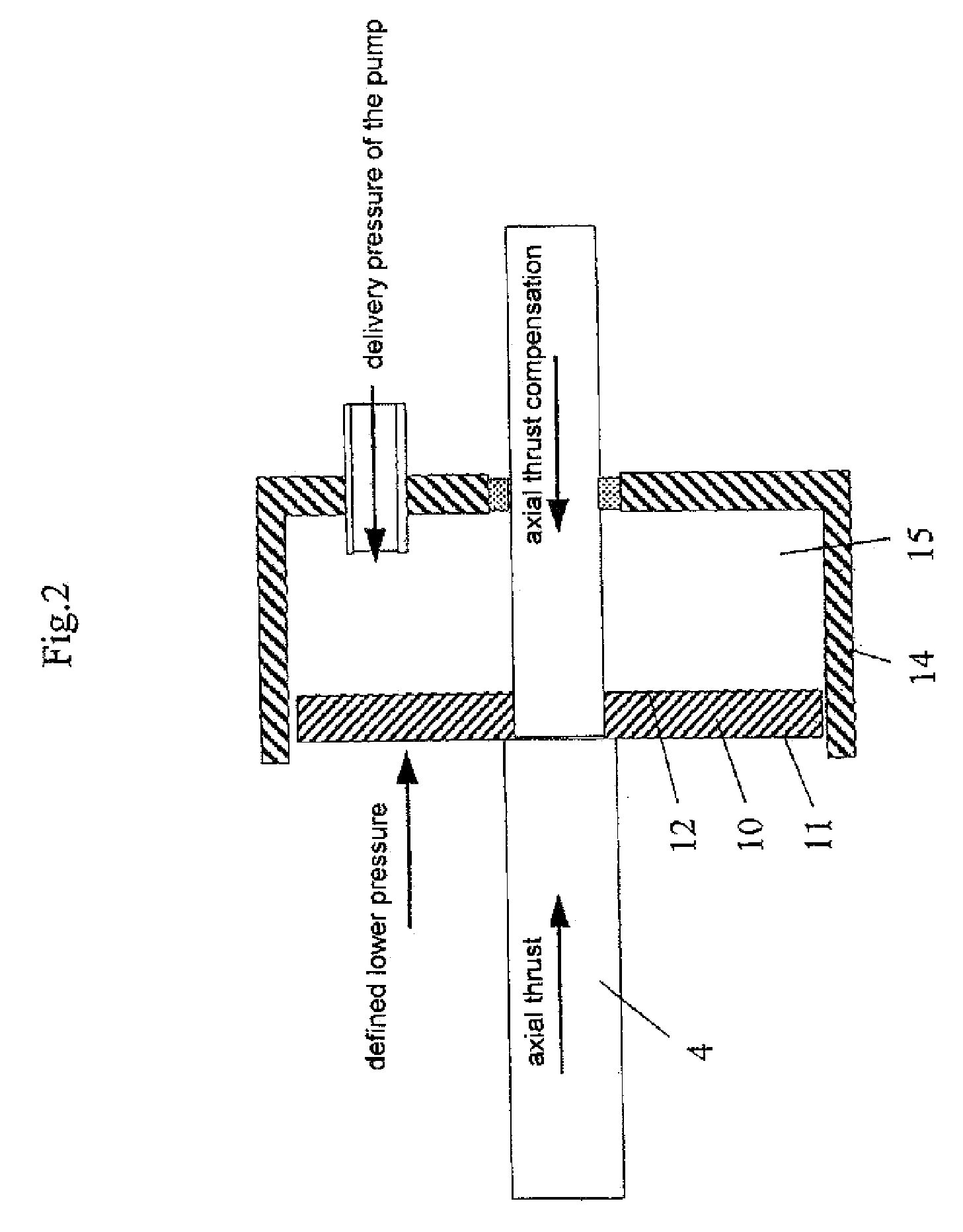
[0013]In an embodiment to reduce the loading on the thrust bearings a compensating piston which at least partially supports the axial thrust is connected to the shaft in force-locking relationship in the axial direction of the shaft. That permits the pump / drive unit to be of a very compact structure, in which, in operation of the pump, the compensating force which counteracts the axial thrust is transmitted directly and without loss to the shaft of the drive unit.
[0033]The method of retrofitting an arrangement for the compensation of the axial thrust makes it possible to equip conventional pumps with the arrangement according to the invention so that those pumps can also enjoy the above-mentioned advantages. The method of retrofitting axial thrust compensation on a pump comprising at least one rotary pump unit and at least one drive unit for the rotary pump has for that purpose: mounting a piston to the pump shaft; mounting to the pump a cylinder for guiding the piston; producing a feed for the pump pressure produced in operation to the side of the piston which faces in the direction of the axial thrust; producing a feed for a predetermined lower pressure than the pump pressure to the other side of the piston, wherein one of the feeds is an axial passage in the shaft; and setting up the assembly of the piston and the cylinder so that in operation of the pump a pressure difference can thus be self-regulatingly produced, wherein a force which is dependent on the axial thrust of the pump and which is in opposite relationship thereto acts on the shaft by means of the pressure difference at the pump shaft.

Problems solved by technology

Due to the loading on the thrust bearings the axial thrust increases the wear thereof and thus shortens the service life of the bearings.
The efficiency of the pump is also adversely affected.
That signifies a considerable increase in the complication and expenditure in terms of manufacture and operation.
Furthermore each additional device also always represents a possible source of defect and failure, which gives rise to additional costs due to repair and maintenance.

Method used


Image

  • Device and procedure for axial thrust compensation
  • Device and procedure for axial thrust compensation
  • Device and procedure for axial thrust compensation

Examples


Embodiment Construction

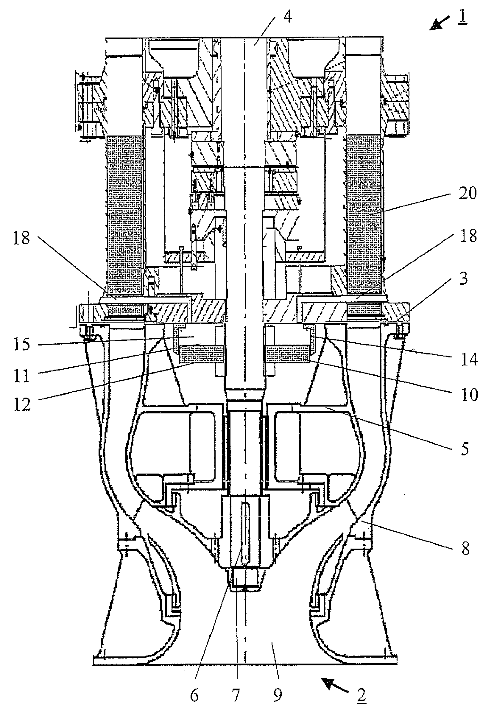
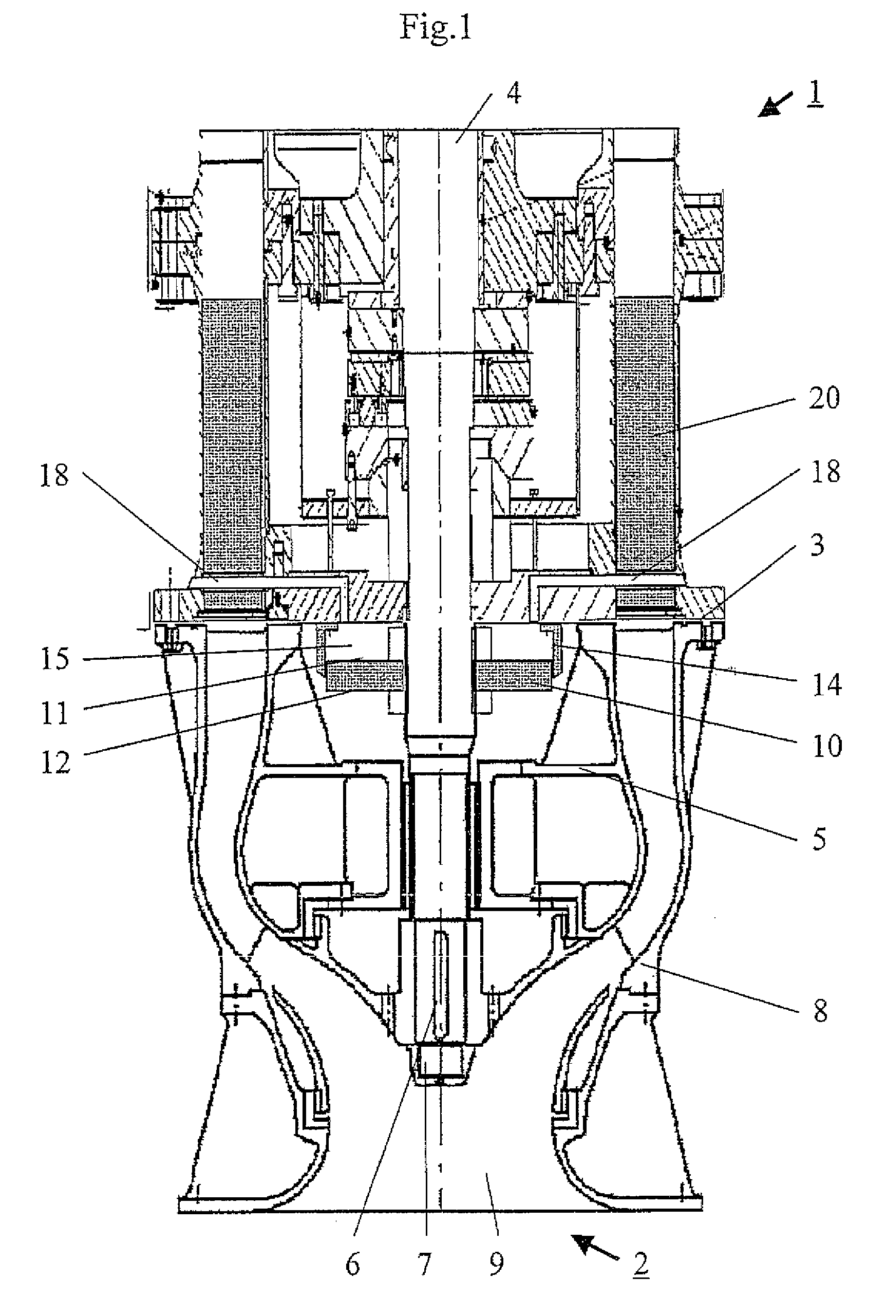
[0041]FIG. 1 shows an embodiment by way of example of a vertical pump. In this connection, in the simplest case the term vertical pump is used to denote the combination of a drive unit with a rotary pump unit, which are arranged one above the other substantially perpendicularly to the level on which the pump stands. As noted in the opening part of this specification, the term vertical pump is used here to denote a pump in which in use the pump shaft is oriented substantially vertically. Furthermore it should be established for clarification purposes that, for a vertical pump, when pumping a fluid against the force of gravity ‘down’ is defined in relation to the vertical pump by the suction side of the pump unit and correspondingly ‘up’ in relation to the vertical pump corresponds to the pressure side of the pump unit.

[0042]The vertical pump shown in FIG. 1 comprises a drive unit 1 which can be for example an electric motor and a rotary pump unit 2 which is fixed to the drive unit 1 ...


PUM


Abstract

Compensation for the axial thrust in a pump, in particular a vertical pump, having at least one drive unit and at least one rotary pump unit. In operation of the pump a compensating piston which is axially non-displaceably connected to the shaft of the impeller wheel of the rotary pump unit is subjected to a pressure difference which results from the pump pressure and a lower pressure and from which there is produced a force which is directed in opposite relationship to the axial thrust and which acts on the shaft of the impeller wheel. There are further proposed a method of axial thrust compensation and a method of retrofitting an arrangement for axial thrust compensation to a pump, in particular a vertical pump, and a retrofit module therefore.

Description

FIELD OF THE INVENTION[0001]The invention generally concerns a pump, in particular a vertical pump, a procedure for or method of compensating for the axial thrust which occurs in operation in a pump, and a method of retrofitting axial thrust compensation to a pump and a corresponding retrofit module for axial thrust compensation on a pump.BACKGROUND OF THE INVENTION[0002]The pumps being considered here have at least one impeller wheel which is driven by way of a shaft by at least one drive unit, wherein in operation an axial thrust corresponding to the pump pressure acts on the shaft of the impeller wheel. The term vertical pump is used here to denote a pump in which in use the pump shaft is oriented substantially vertically.[0003]As mentioned hereinbefore, a force acting in the axial direction, referred to as axial thrust, acts on the shaft of the pump in operation thereof. That force results from the loading of the pump impeller wheel or wheels by the fluid to be delivered and is ...

Claims


Application Information

Patent Timeline
IPC IPC(8): F01D3/04
CPCF04D29/0416
Inventor NEISZER, JOHANN
Owner RITZ PUMPENFAB
Learn More