Image processing device, jpb processing method, and program
a processing method and image technology, applied in the field of image processing devices and jpb processing methods, can solve the problems of high cost and high cost for users, and achieve the effect of reducing cost and smooth job processing
- Summary
- Abstract
- Description
- Claims
- Application Information
AI Technical Summary
Benefits of technology
Problems solved by technology
Method used
Image

Examples
embodiment 1
[0047]Details, in structure, of the image processing device of the present embodiment and the image processing system including the image processing device will be described in the following.
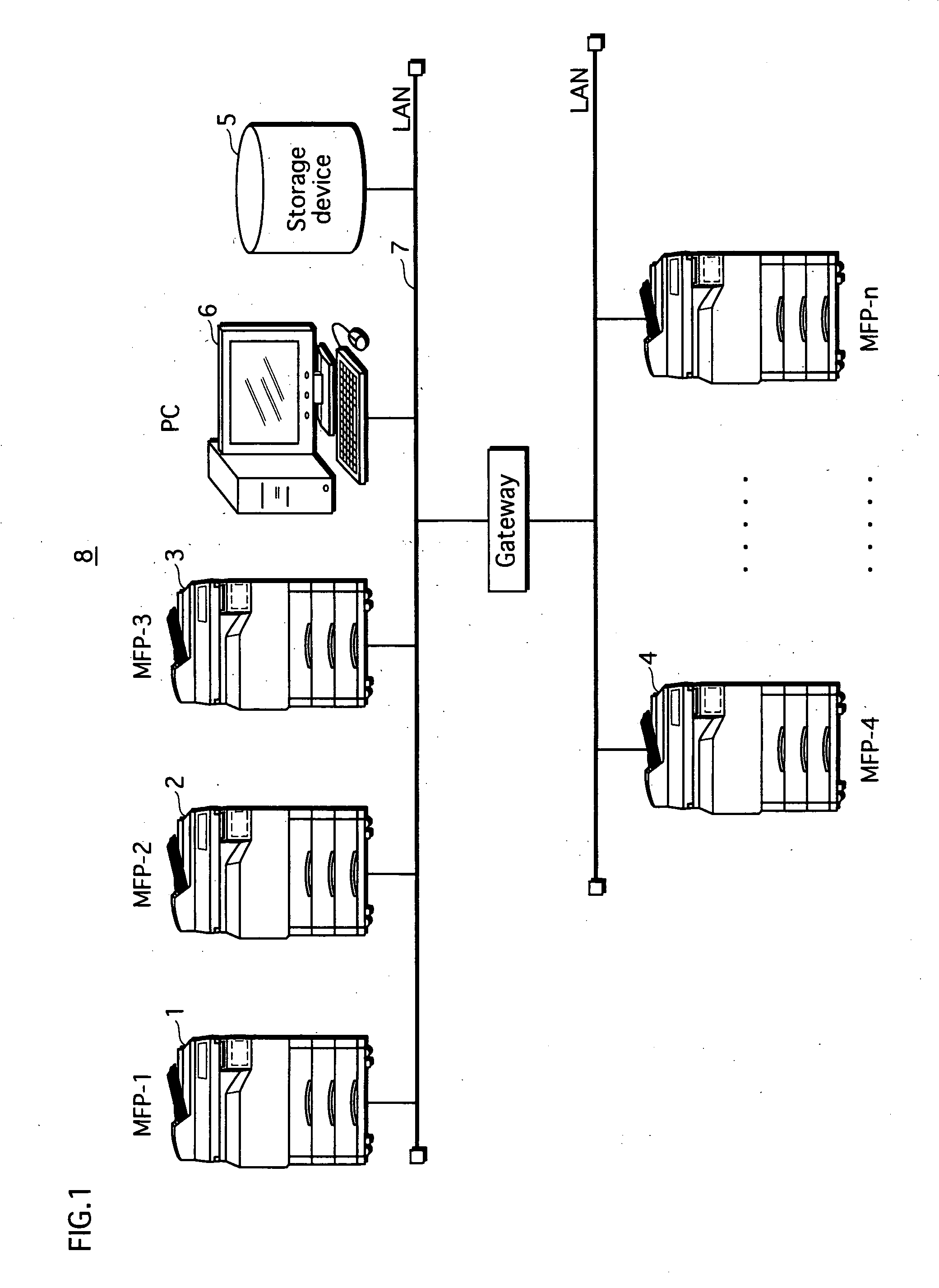
[0048]FIG. 1 schematically shows the overall structure of an image processing system 8.
[0049]As shown in FIG. 1, the image processing system of Embodiment 1 includes MFPs (Multiple Function Peripherals) 1, 2, 3, 4, . . . , a storage device 5, and a PC (Personal Computer) 5, which are connected with each other via a network 7 that is a LAN or the like. It should be noted here that the image processing system may be connected with, for example, a FAX machine and a printer, as well as with the MFPs 1, 2, 3, 4, . . . , the storage device 5 and the PC 6.
[0050]Each of the MFPs 1, 2, 3, 4, . . . receives a request for processing a job, such as a copy, print, or scan from the user, and processes the job. The MFPs 1, 2, 3, 4, . . . will be described in detail later.
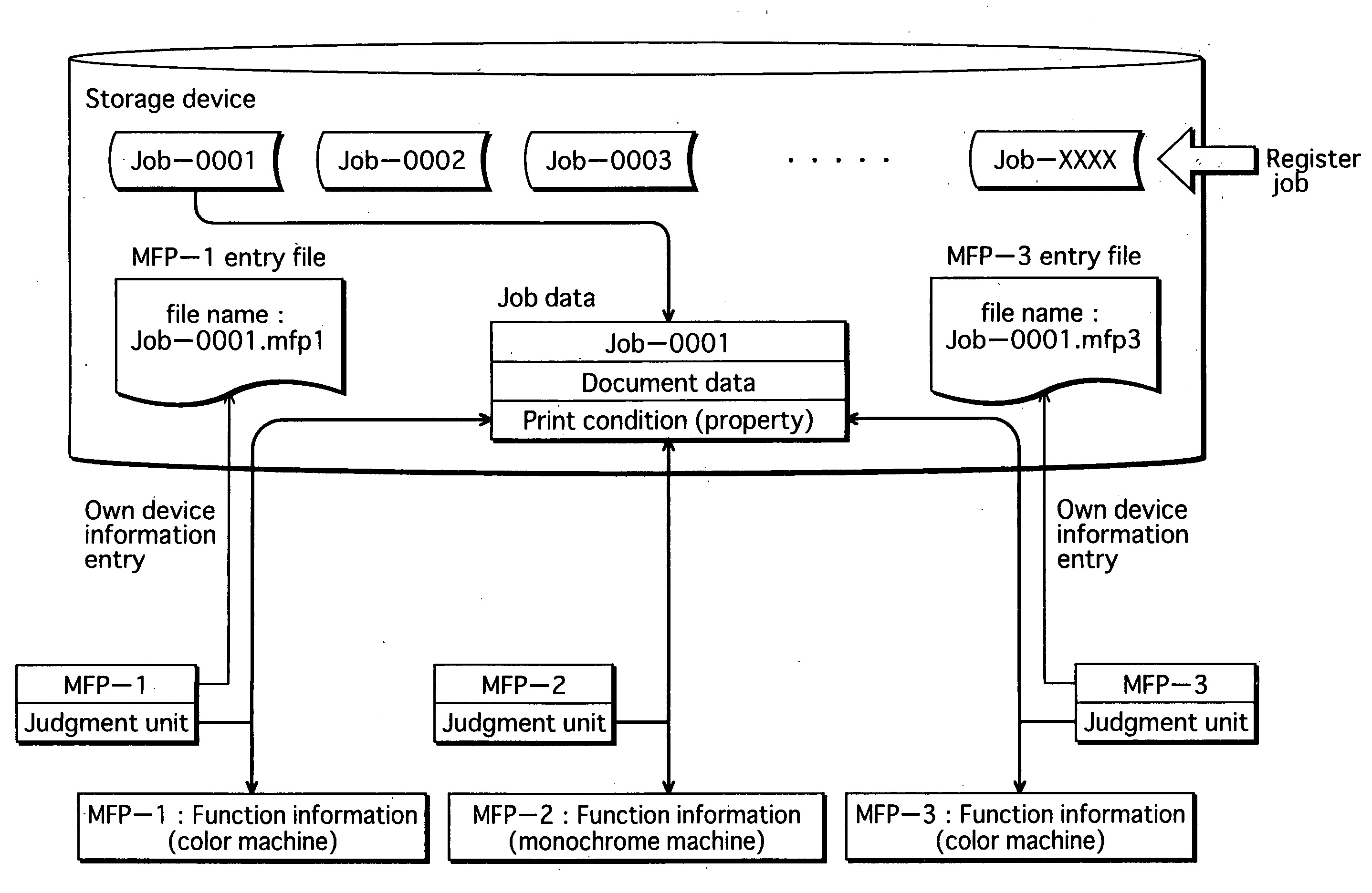
[0051]The sto...
embodiment 2
[0179]In Embodiment 1 described above, all the MFPs perform the job check at the same cycle. Embodiment 2 differs from Embodiment 1 in that the MFPs perform the job check not necessarily at the same cycle. In the following, to avoid redundancy, the description having already been provided in Embodiment 1 is omitted, and the same reference numbers are used for the constituent elements that are common with Embodiment 1.
[0180]FIG. 21 is a sequence diagram showing a detailed operation of the image processing system in Embodiment 2. It should be noted here that, in FIG. 21, the job judgment processing unit 96 and the access timer management unit 97 are respectively indicated in abbreviated forms “judgment unit” and “management unit”.
[0181]The access timer management units 97 of each of the MFPs 1, 2, and 3 generate an access timing signal at a predetermined cycle. The job judgment processing unit 96 of each of the MFPs 1, 2, and 3 confirms at a predetermined cycle whether there is an unp...
embodiment 3
[0191]The image processing system of Embodiment 3 differs from that of Embodiment 1 in that, if an image processing device judges in the second judgment that the own device is equal, neither advantageous nor disadvantageous, in comparison with the other devices, the image processing device adds a new piece of information for the judgment, and if the image processing device judges that the own device is advantageous in comparison with the other devices with respect to the newly added information, the image processing device processes the job.
[0192]FIGS. 22A and 22B show examples of entry files in the present embodiment. FIG. 22A shows entry files before information is newly added, and FIG. 22B shows entry files after information is newly added.
[0193]For example, if the entry files of the MFP 1 and MFP 3 are the same as shown in FIG. 22A, the job judgment processing units 96 of the MFP 1 and MFP 3 judge that the MFP 1 and MFP 3 are equal, and suspend the judgment on whether the own de...
PUM
 Abstract
Description
Claims
Application Information
 - R&D
- Intellectual Property
- Life Sciences
- Materials
- Tech Scout
- Unparalleled Data Quality
- Higher Quality Content
- 60% Fewer Hallucinations
Browse by: Latest US Patents, China's latest patents, Technical Efficacy Thesaurus, Application Domain, Technology Topic, Popular Technical Reports.
© 2025 PatSnap. All rights reserved.Legal|Privacy policy|Modern Slavery Act Transparency Statement|Sitemap|About US| Contact US: help@patsnap.com