
Maximum likelihood detection method and system

a probability detection and probability detection technology, applied in the field of wireless communication, can solve the problems of high complexity of the method, inability to implement the practice, and variable decoding latency, and may be quite long

Active Publication Date: 2008-07-31
IND TECH RES INST
View PDF21 Cites 50 Cited by
  • Summary
  • Abstract
  • Description
  • Claims
  • Application Information

AI Technical Summary

Problems solved by technology

Such a high-complexity method, however, may in practice be impossible to implement.
With respect to the depth-first sphere decoding, the decoding latency varies much and may be quite long at lower SNR, which is not acceptable for real-time systems.

Method used


Image

  • Maximum likelihood detection method and system
  • Maximum likelihood detection method and system
  • Maximum likelihood detection method and system

Examples


Embodiment Construction

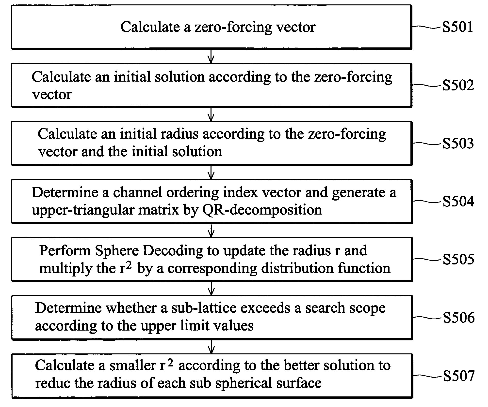
[0033]Several exemplary embodiments of the invention are described with reference to FIGS. 4 through 6, which generally relate to maximum likelihood detection. It is to be understood that the following disclosure provides various different embodiments as examples for implementing different features of the invention. Specific examples of components and arrangements are described in the following to simplify the present disclosure. These are, of course, merely examples and are not intended to be limiting. In addition, the present disclosure may repeat reference numerals and / or letters in the various examples. This repetition is for the purpose of simplicity and clarity and does not in itself dictate a relationship between the various described embodiments and / or configurations.

[0034]The invention discloses a maximum likelihood detection (MLD) method and system.

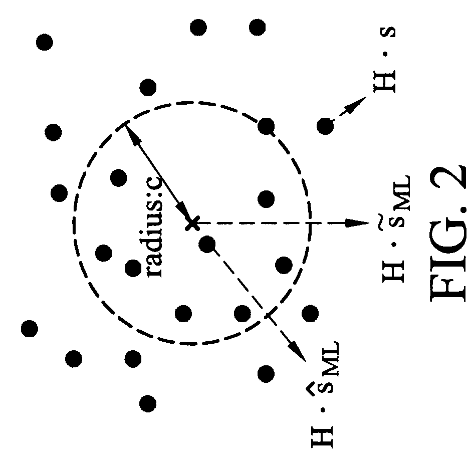
[0035]The sphere decoding is introduced to MIMO technology to reduce the complexity of MLD. The sphere decoding first defines ...


PUM


Abstract

A maximum likelihood detection (MLD) method is disclosed. Received data is processed to obtain preliminary parameters. An initial radius r is determined. r2 is multiplied by a corresponding scaling factor according to a partial Euclidean distance (PED) constraint function to determine the upper limit values of PED for each layer. It is examined whether a sub-lattice exceeds a search scope according to the upper limit values of PED for each layer to search a better solution by utilizing the preliminary parameters.

Description

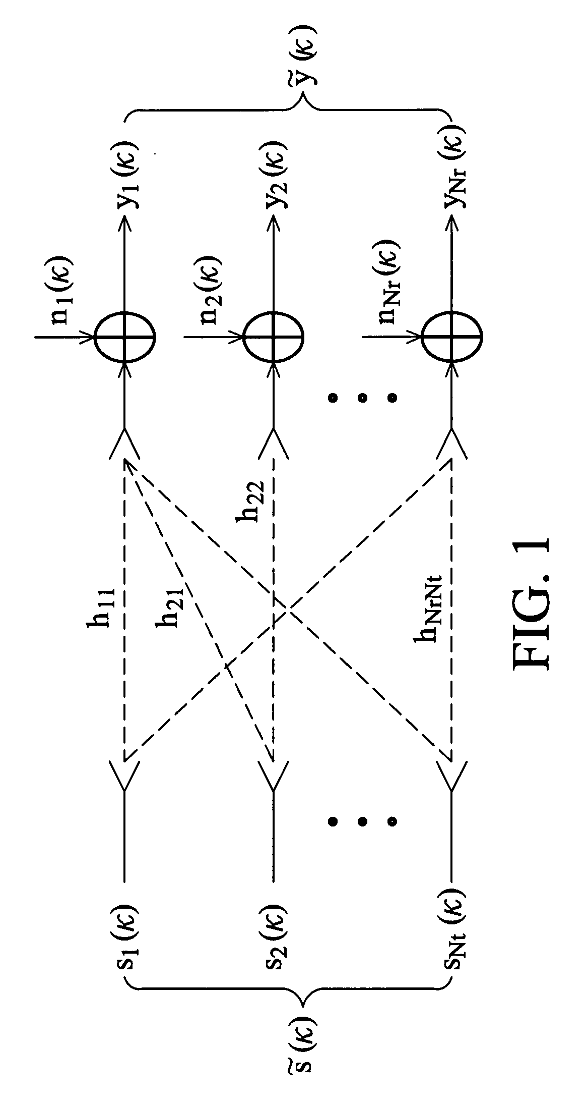
BACKGROUND OF THE INVENTION[0001]1. Field of the Invention[0002]The invention relates to wireless communication, and more particularly to a maximum likelihood detection (MLD) method and system, applying a sphere decoder to multiple-input multiple-output (MIMO) technology.[0003]2. Description of the Related Art[0004]MIMO is an abstract mathematical model for multi-antenna communication systems. MIMO technology has attracted the attention of wireless communications developers, because it significantly increases transmission throughput and range at the same bandwidth and same overall transmitting power. In general, MIMO technology increases the spectral efficiency of a wireless communication system. MIMO exploits the multipath scattering effect to increase data throughput and range, or reduce bit error rate, rather than attempting to eliminate it as in conventional SISO (Single-Input Single-Output) communication systems. MIMO can also be used in conjunction with Orthogonal Frequency Di...

Claims


Application Information

Patent Timeline
Patent Type & Authority Applications(United States)
IPC IPC(8): H03D1/00H04L27/06H04L23/02
CPCH04L25/03242
Inventor CHEN, CHIN-HUNGHSIEH, YU-TAOHSU, JEN-YUANTING, PANG-AN
Owner IND TECH RES INST
Learn More