Image forming apparatus and method of transferring print data

Inactive Publication Date: 2008-07-31
FUJIFILM CORP
View PDF5 Cites 20 Cited by
  • Summary
  • Abstract
  • Description
  • Claims
  • Application Information

AI Technical Summary

Benefits of technology

[0012]The present invention has been contrived in view of these circumstances, an object thereof being to provide an image forming apparatus which is capable of achieving high-speed transfer of print data to the recording head at low cost, and to a method of transferring print data used in such an apparatus.
[0018]According to the above-described aspects of an image forming apparatus and a method of transferring print data used in same according to the present invention, the data corresponding to mutually adjacent recording elements of a matrix type head in the image buffer memory is rearranged so as to be stored at consecutive addresses, in accordance with the adjacency relationships in the arrangement of recording elements in the matrix type head; therefore when print data is read out from the image buffer memory and transferred to the head, the memory reading efficiency is good and high-speed data reading and high-speed data transfer can be achieved.
[0021]According to the above-described aspects of the present invention, since the read-out of print data from the memory is efficient, then the image page memory can be located in the host computer and data read-out from this image page memory can be carried out via the communications interface of the host computer (for example, USB, IEEE 1394, or the like). In this case, there is no need to provide an image page memory for one page in the printer, and therefore costs can be reduced yet further.
[0030]According to the present invention, since print data can be read out efficiently from the consecutive addresses from the image buffer memory, then high-speed read-out and the high-speed transfer can be achieved. Furthermore, since the memory can be composed readily by means of an inexpensive DRAM, then it is possible to reduce costs.

Problems solved by technology

(4) The fact that the read-out addresses from the memory are dispersed in a scattered fashion (random read-out) and that the read-out efficiency is poor does not pose a significant problem when the speed of the printer is slow (e.g., if the head has a small number of nozzles, or if the driving frequency of the head is low), but if high-speed characteristics are required in the printing apparatus, for instance, if the apparatus is constituted so as to print at high speed by means of a full line type of head having the width of a page, then the memory read-out speed and data transfer speed do present an obstacle to achieving high-speed performance.
In the case of an oblique nozzle arrangement as disclosed in Japanese Patent Application Publication No. 2006-44150, it is possible to adopt a composition based on a shift register because the interval between nozzles is approximately several pixels, but in the case of a matrix type of head, since the intervals between the nozzles are large (several tens of pixels or greater), then it is necessary to prepare a shift register of large volume which can be accessed at high speed, and this is not practicable.
Furthermore, in Japanese Patent Application Publication No. 2006-44150, it is stated that “the aforementioned problem can be resolved by aligning the horizontal print data in accordance with the nozzle arrangement in a higher-level apparatus and then rearranging the data arrangement according to the ejection sequence of the nozzles, but the rearranging process described above is problematic in that it cannot keep pace with increase in the printing speed of the inkjet printing apparatus”.

Method used


Image

  • Image forming apparatus and method of transferring print data
  • Image forming apparatus and method of transferring print data
  • Image forming apparatus and method of transferring print data

Examples


further embodiment

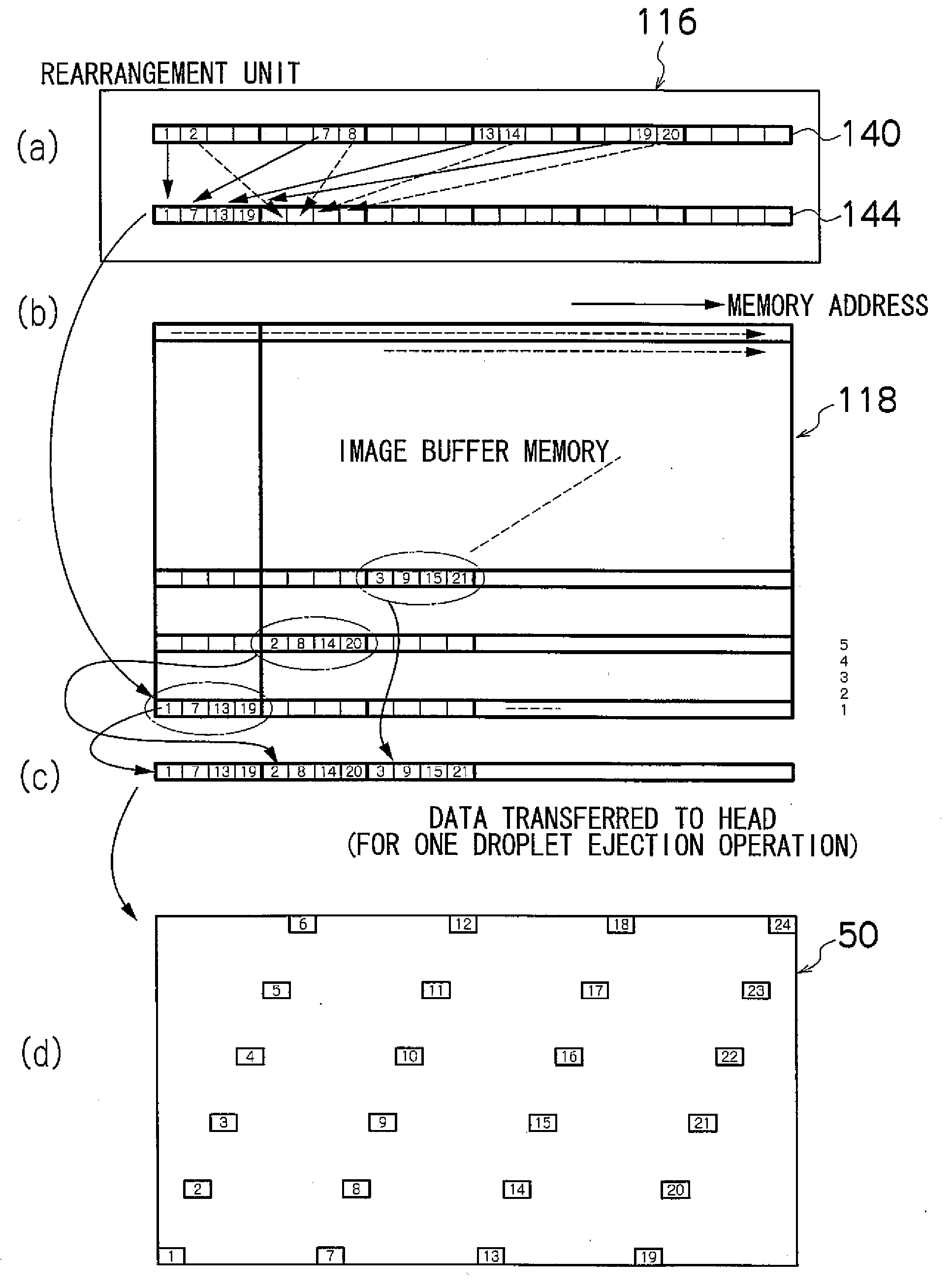
[0134]The compositions shown in FIG. 6 to FIG. 12 comprise an image page memory 114 provided inside the printer. When handling images of high resolution, this image page memory 114 becomes extremely large in volume. For example, in the case of a system which reproduces images of 1200×1200 dpi resolution in six colors and four tones for each color, it is expected that a memory of 200 MB capacity will be required.

[0135]On the other hand, it is also possible to adopt a composition in which an image page memory is not provided inside the printer, as shown in FIG. 14. More specifically, in the composition shown in FIG. 14, the image data (print data) is transferred to the printer, one line at a time, from a page memory 180 inside the host computer 101. In FIG. 14, elements which are the same as or similar to those of the composition shown in FIG. 12 are labeled with the same reference numerals and description thereof is omitted here.

[0136]In the case of the composition shown in FIG. 14, ...


PUM


Abstract

An image forming apparatus includes: a rearrangement device having a configuration whereby the print data is rearranged in such a manner that data of pixels corresponding to mutually adjacent recording elements which are aligned on a straight line in the second direction in the recording head is located within a same word or within adjacent words; and an image buffer memory having at the least a storage capacity of storing the print data rearranged by the rearrangement device for an image region corresponding to a surface area occupied by a plurality of recording elements arranged in a two-dimensional matrix configuration in a recording head.

Description

BACKGROUND OF THE INVENTION[0001]1. Field of the Invention[0002]The present invention relates to an image forming apparatus and a method of transferring print data, and more particularly, to an image forming apparatus based on a dot recording method, such as an inkjet printer, and technology for efficiently transferring the print data used in such an apparatus.[0003]2. Description of the Related Art[0004]In the field of inkjet printers, a so-called matrix type of inkjet head in which nozzles are arranged in a two-dimensional array in order to eject ink droplets is well known. In a matrix type of head of this kind, it is necessary to make the interval between nozzles greater than the interval between pixels, due to the requirements of arrangements of the pressure chambers and the flow channels, and therefore the adjacency relationship between the nozzles which are mutually adjacent in the head and the pixels of the print dots which are mutually adjacent on the recording medium (on th...

Claims


Application Information

Patent Timeline
IPC IPC(8): B41J29/38
CPCG06K15/02B41J29/393
Inventor OKU, SEIICHIRO
Owner FUJIFILM CORP
Why Eureka
Try Eureka