
Battery-less power generation control system and straddle type vehicle having the same

a power generation control and battery-less technology, applied in the direction of electric generator control, dynamo-electric converter control, machines/engines, etc., can solve the problems of excess current flow through the circuit, excess current needlessly flows through the circuit, and fuel economy deterioration, so as to improve fuel economy and reduce any horsepower loss

Inactive Publication Date: 2008-07-31
YAMAHA MOTOR ELECTRONICS CO LTD
View PDF0 Cites 6 Cited by
  • Summary
  • Abstract
  • Description
  • Claims
  • Application Information

AI Technical Summary

Benefits of technology

"The patent text describes a battery-less power generation control system for vehicles that can supply sufficient current to electric equipment without losing much of the power generated by the engine. This system can maintain good fuel economy and can be used in kick starter type motorcycles or the like. The system includes a magnet-type generator driven by the engine and a load current detecting sensor to detect the current flowing through the electric device. A controller rectifies the generated alternating current to a direct current and supplies it to the electric device. The controller also controls the output of the generated current so that it is generally equal to the load current. The method involves detecting the load current, inputting it into the controller, and adjusting the generated current accordingly to maintain a balance between the load current and the generated current."

Problems solved by technology

Hence, there is some risk that a current which exceeds the current necessary for the other loads flows through the circuit.
If this occurs, the excess current needlessly flows through the circuit.
Consequently, there can be other risks that the fuel economy deteriorates and some losses arise with the horsepower generated in accordance with the engine operation.

Method used


Image

  • Battery-less power generation control system and straddle type vehicle having the same
  • Battery-less power generation control system and straddle type vehicle having the same
  • Battery-less power generation control system and straddle type vehicle having the same

Examples


Embodiment Construction

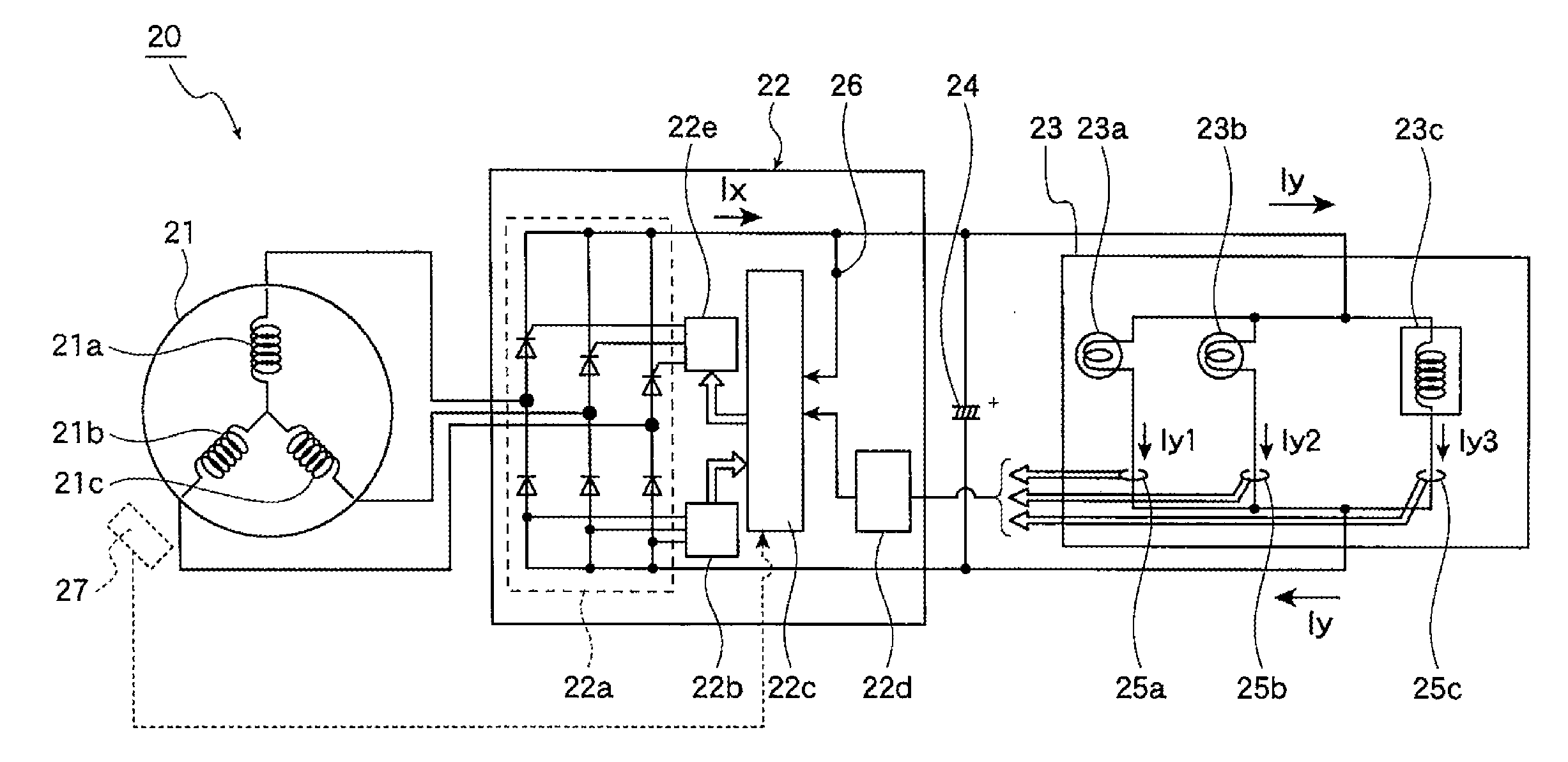
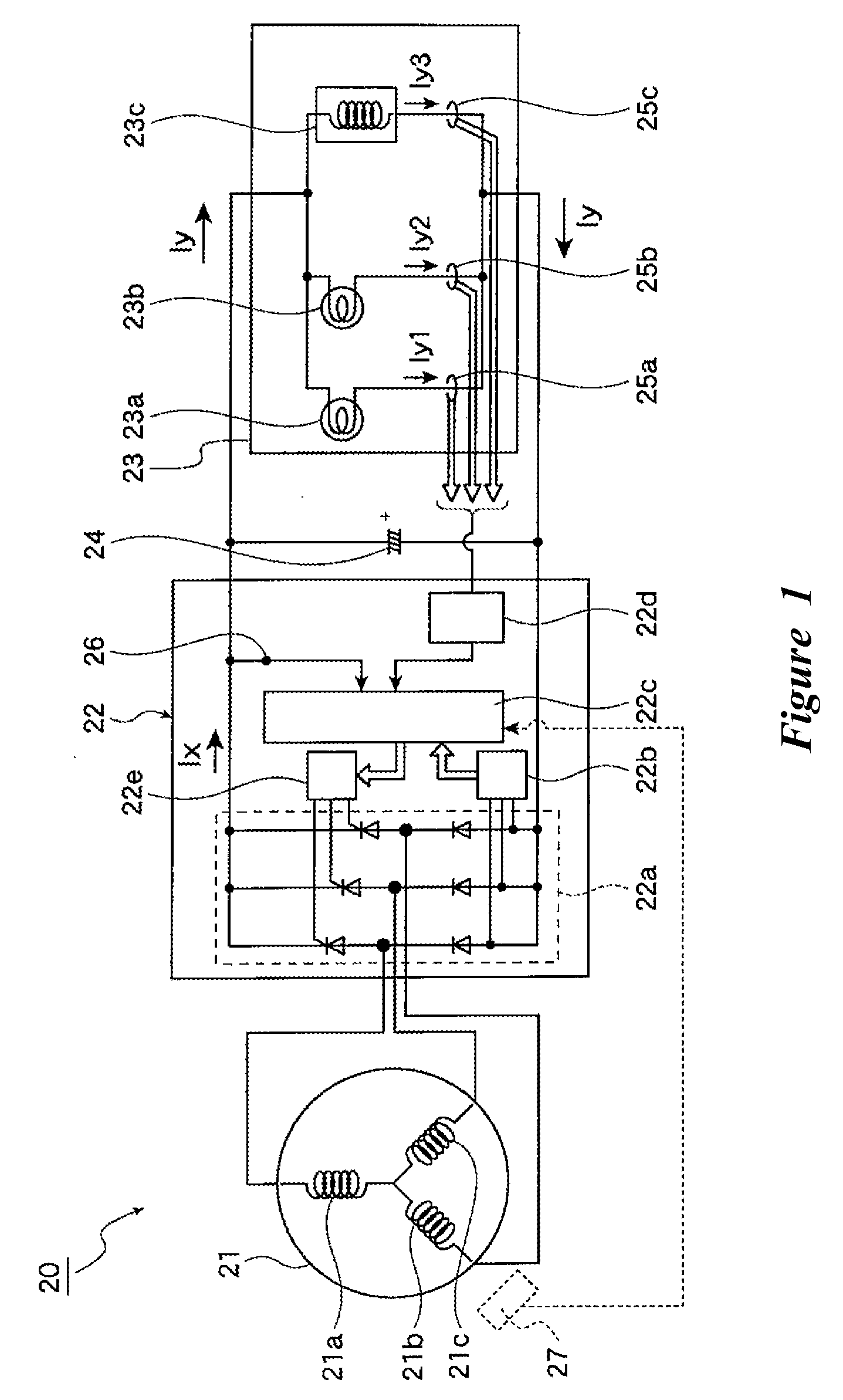
[0034]FIG. 1 shows one embodiment of a battery-less power generation control system 20, which can be used with a straddle type vehicle, such as, for example, a motorcycle or the like. However, the inventions disclosed herein are not limited to a so-called motorcycle-type two-wheel vehicle, but are applicable to other types of two-wheel vehicles. Moreover, the inventions disclosed herein are not limited to two-wheel vehicles, but may be used with other types of straddle-type vehicle. Furthermore, some aspects of the inventions disclosed herein are not limited to straddle-type vehicles, but can also be used with vehicles with side-by-side seating.

[0035]As shown in FIG. 1, the battery-less power generation control system 20 includes a magnet type generator 21, a generated-current controller 22, electric equipment 23, and a capacitor 24 disposed parallel to the electric equipment 23.

[0036]The magnet type generator (e.g., power generating body) 21 can be a three-phase alternating current...


PUM


Abstract

A battery-less power generation control system that maintains fuel economy and minimizes losses in horsepower generated by engine operation includes a magnet-type generator driven by an internal combustion engine and a controller for rectifying the alternating current generated by the generator to a direct current, the controller supplying the generated direct current to electric equipment. The controller includes a rectifying section for converting the alternating current generated by the generator to direct current, and a control section for controlling the generated current output by the rectifying section. The battery-less power generation control system detects a load current flowing through the electric equipment and the control section controls the rectifying section so that the generated current is generally equal to the load current.

Description

CROSS-REFERENCE TO RELATED APPLICATIONS[0001]This application is based upon and claims priority under 35 U.S.C. § 119 to Japanese patent application Serial No. 2007-022128, filed Jan. 31, 2007, the entire contents of which is hereby incorporated by reference.BACKGROUND OF THE INVENTION[0002]1. Field of the Invention[0003]The present invention relates to a power generation control system. Embodiments of the invention are disclosed herein as a battery-less power generation control system in which alternating current is generated by a magnet type generator using an internal combustion engine as a drive source, the alternating current is rectified to direct current by generated current control means, and the direct current is supplied to electric equipment, and a straddle type vehicle having the battery-less power generation control system that can be applied to a kick starter type motorcycle or the like.[0004]2. Description of the Related Art[0005]FIG. 6 is a circuit diagram of a conve...

Claims


Application Information

Patent Timeline
Patent Type & Authority Applications(United States)
IPC IPC(8): H02P9/00
CPCF02P1/02H02P9/48F02P13/00H02M1/0085
Inventor SATO, KAZUO
Owner YAMAHA MOTOR ELECTRONICS CO LTD
Learn More