Wastewater flow equalization system and method

a wastewater flow and equalization system technology, applied in the direction of sedimentation settling tanks, multi-stage water/sewage treatment, separation processes, etc., can solve the problems of process failure, high undesired, and most definitely the extreme push of the original wastewater treatment installation

Active Publication Date: 2008-07-31
GRAVES JAN D
View PDF27 Cites 8 Cited by
  • Summary
  • Abstract
  • Description
  • Claims
  • Application Information

AI Technical Summary

Benefits of technology

[0007]In keeping with the present invention, under physical inspection during scheduled maintenance or repair or upon an automatic alarm, the less than desired efficiency of the design flow equalization ports is readily observed, particularly by the maximum height or maximum range of heights of wastewater reflected upon an exterior surface of the filter member surrounding the peripheral wall containing the flow equalization ports. Solids filtered from the wastewater which do not pass through this filter accumulate upon the exterior thereof to a greater or lesser degree depending upon the upstream head as induced by the pair of design flow equalization ports. If the pair of flow equalization ports are undersized, the “normal” operating liquid level of the wastewater will rise together with solids which accumulate on the upstream side (outside) of the filter. If upon examination of the filter, an extremely high liquid level is observed because of the large amount of solids / sludge / biosolids / scum layer or mat deposited upon the exterior of the filter above the design flow equalization ports, the service personnel knows intuitively and through experience that the design flow equalization ports are undersized. The flow port members are simply removed and both are replaced by a flow port member having a larger flow equalization port than those first installed in the wastewater treatment mechanism. As one example, each of the initial flow port members might have a flow equalization port of ¼″ diameter which might be considered, for example, the “standard” design flow equalization port size formed in a “standard” flow port member of a “standard” 1¾″ outer diameter accommodated in like sized openings of the container peripheral wall. The service personnel, having quickly recognized from the observed high level or high range of levels of the solids / particulates / scum upon the filter would therefrom necessarily determine that the original design flow equalization ports are now “undersized” to achieve present day (increased family size) flow demands. The pair of flow port members would be removed and, based upon judgment and experience, would each be replaced by another flow port member having a larger design flow equalization port, such as 5 / 16″, ⅜″, 7 / 16″, and in reality any diameter up to and virtually including the 1¾″ diameter of the peripheral wall openings. By so readily and easily removing and replacing one, two or more flow port members with desired sizes / diameters of flow equalization ports otherwise inefficient flow equalization of the wastewater treatment system is rendered very efficient in an inexpensive and rapid fashion.

Problems solved by technology

However, should this hypothetical family grow to include an additional four children, the original wastewater treatment installation might be severely taxed and, instead of operating at its most efficient level (design flow equalization ports), it might operate predominantly under overflow conditions (peak flow equalization ports) which is highly undesired.
If the original house assumed to have the three bedrooms, four occupants, etc. was expanded to include further bathroom facilities and should bathroom, shower and clothes washing increase as children grow older and / or the number of children increase the original wastewater treatment installation would most definitely be pushed to the extreme and process failure could occur.
However, as is customary during scheduled maintenance and inspection of wastewater treatment mechanisms or upon automatically generated alarms therefrom, it might well become apparent that the design flow equalization ports are operating inefficiently, particularly years after installation and as the hypothetical family has grown, its numbers increase and wastewater flow correspondingly appreciably increases.

Method used


Image

  • Wastewater flow equalization system and method
  • Wastewater flow equalization system and method
  • Wastewater flow equalization system and method

Examples


Embodiment Construction

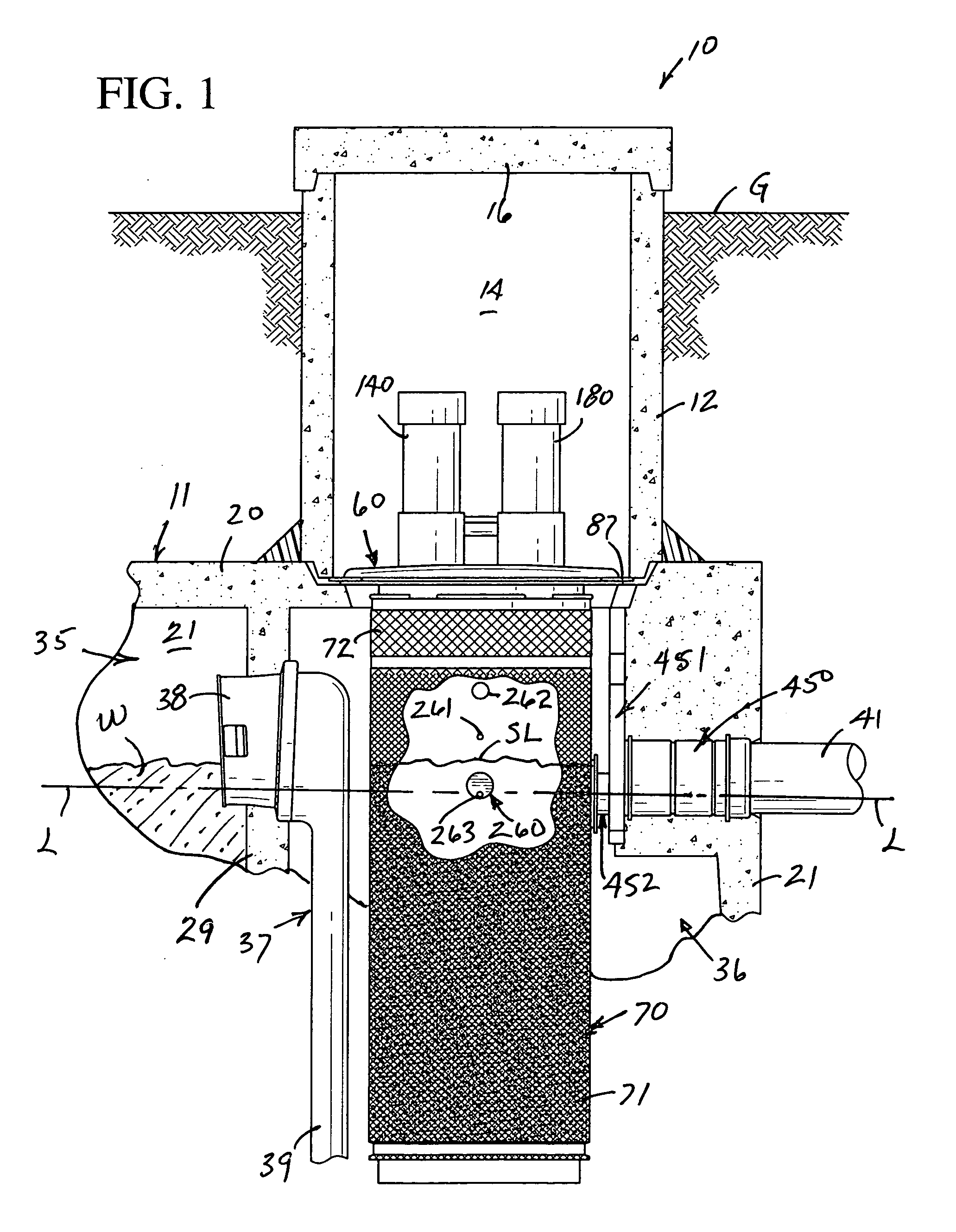
[0021]The novel apparatus, mechanism and method disclosed specifically hereinafter includes improvements in the wastewater treatment plant of U.S. Pat. No. 5,413,706 dated May 9, 1995 in the name of Jan D. Graves and assigned to Norwalk Wastewater Equipment Company (NORWECO), and the totality of the disclosure of the latter patent is incorporated herein by reference. Much of comparable elements of the latter patent which correspond to elements herein will be described briefly utilizing identical reference numerals to thereby assure compliance with 35 U.S.C. §112, the first paragraph thereof.

[0022]In keeping with the present invention, a novel wastewater treatment plant (FIG. 1) is generally designated by the reference numeral 10 and is normally designed for residential use, such as individual homes, although the same is readily adapted to many other facilities and utilizes well known digestion processes of wastewater or like fluid treatment.

[0023]The wastewater treatment plant 10 in...


PUM

PropertyMeasurementUnit
Flow rateaaaaaaaaaa
Lengthaaaaaaaaaa
Sizeaaaaaaaaaa

Abstract

A wastewater treatment mechanism includes an interior chamber having a peripheral wall preferably provided with two diametrically opposite openings in each of which is received a flow port member having a flow equalization port therein. Depending upon wastewater levels and surges, the flow port members can be removed and replaced by other flow port members of an identical construction, except for different sizes of design flow equalization ports thereof. Therefore, should a wastewater treatment mechanism be installed initially in a wastewater treatment plant with accurately sized flow equalization ports to achieve desired flow characteristics and efficiency, should such flow characteristics change over time because of inefficient flow-through of wastewater, the originally installed flow port members can be readily removed and replaced with identical flow port members except for larger flow equalization ports thereof thereby returning the overall wastewater treatment mechanism to acceptable design flow equalization and efficiency.

Description

BACKGROUND OF THE INVENTION[0001]This invention is an improvement in wastewater treatment plants or systems, particularly home aeration systems, which experience periodic process upsets of varying load conditions which reduce efficiency. Heretofore the assignee of the present invention patented a wastewater treatment system under U.S. Pat. No. 5,413,706 issued on May 9, 1995 which particularly provided novel flow equalization ports so as to maintain efficiency of the wastewater treatment system even during process upsets or varying load conditions.[0002]In the latter patent the wastewater treatment mechanism 250 of FIGS. 10 through 17 is most representative of prior art and reflects flow equalization provided by three diametrically opposite pairs of vertically spaced flow equalization ports defined by (i) a lowermost diametrically opposite pair of design flow equalization ports, thereabove (ii) a pair of diametrically opposite sustained flow equalization ports, and (iii) a pair of u...

Claims


Application Information

Patent Timeline
IPC IPC(8): C02F1/00
CPCB01D21/0012B01D21/2444C02F1/001C02F1/006C02F2209/40
Inventor GRAVES, JAN D.
Owner GRAVES JAN D
Why Eureka
Try Eureka