
Ultrasonic tubulars inspection device and method

a technology of ultrasonic tubulars and inspection devices, which is applied in the direction of measurement devices, instruments, specific gravity measurements, etc., can solve the problems of all three methods being restricted, and achieve the effect of reducing the number of channels needed, ensuring the effective beam properties, and ensuring the inspection surface area

Inactive Publication Date: 2008-07-31
GIRNDT RICHARD J
View PDF13 Cites 26 Cited by
  • Summary
  • Abstract
  • Description
  • Claims
  • Application Information

AI Technical Summary

Benefits of technology

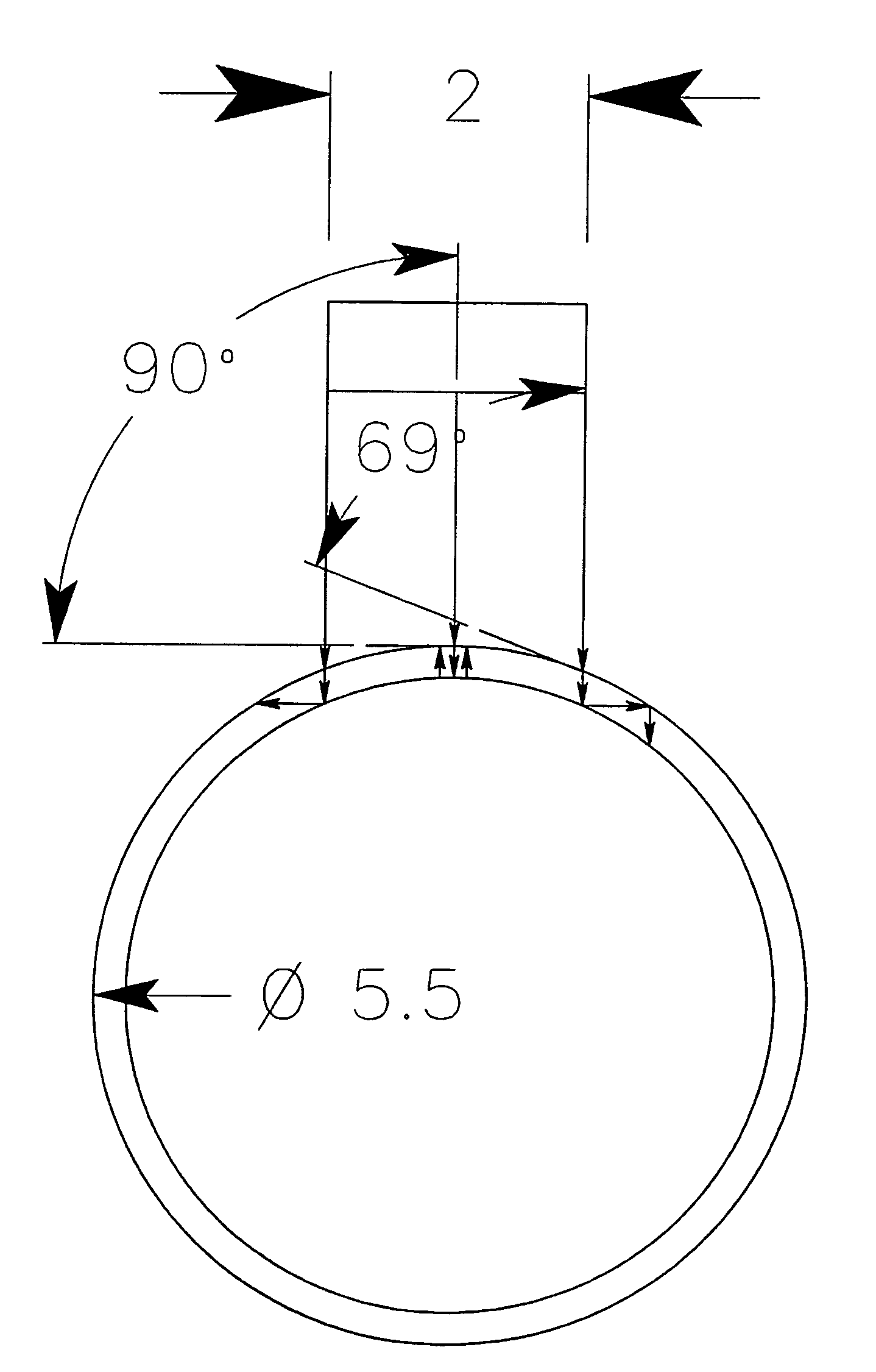
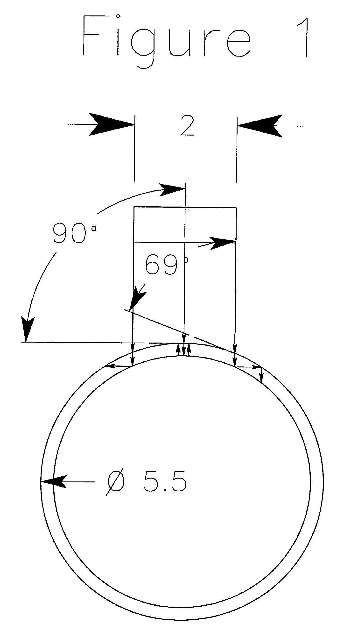
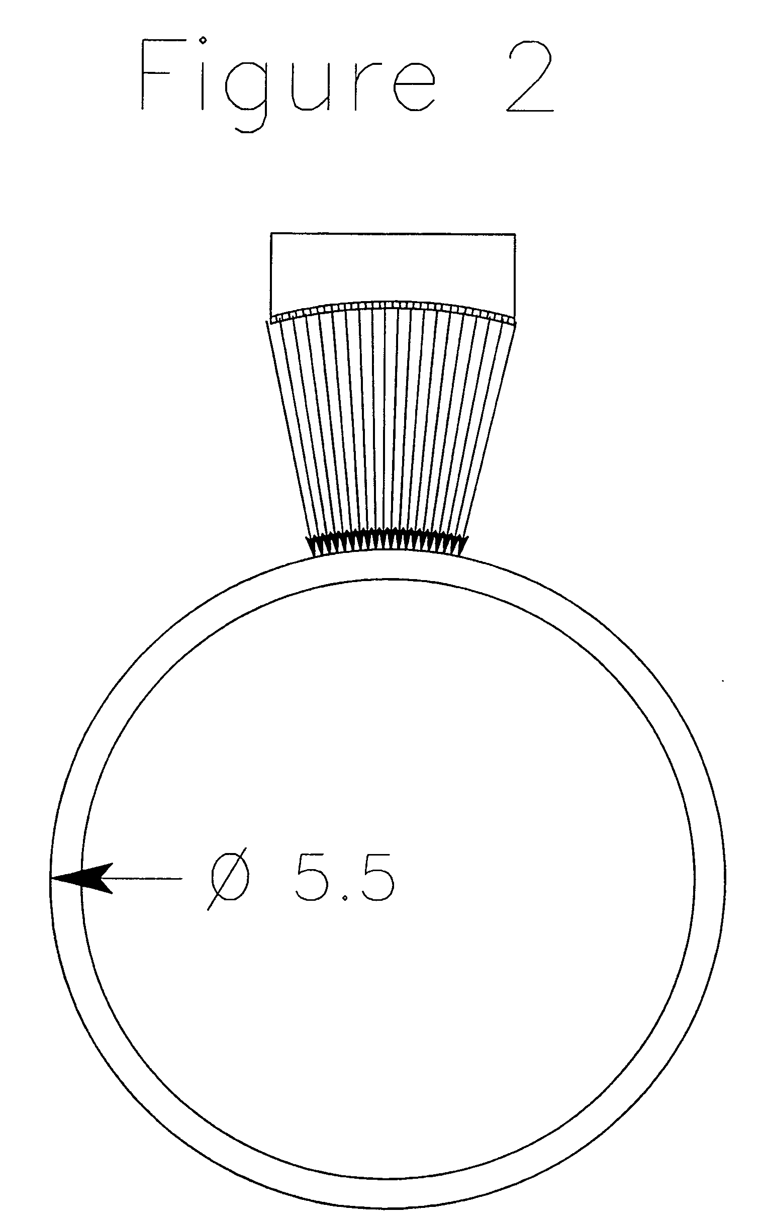
[0017]A system, method, and apparatus for ultrasonic detection of flaws or defects in oil field tubulars utilizing curved composite transducers. An array of curved composite transducers are utilized to detect anomalies in the tubulars, such as transverse, wall or longitudinal defects. The use of the composite transducers allow for a greater inspection surface area per probe over traditional transducers thereby reducing the number of channels needed for inspection of the tubulars.
[0018]The scope of at least one embodiment of the present invention involves using the large sheets of composite material mentioned in the referenced article “Piezocomposite Transducers—A Milestone for Ultrasonic Testing,” not to produce numerous small individual composite transducers, curved to replace a conventional focusing lens, but to produce much larger probes, up to three inches and above, where the entire large single element is curved to a set radius as opposed to the much documented practice of curving smaller elements for focusing purposes. Unlike conventional transducer piezoelectric materials, the new composites can be shaped over a large area while still maintaining the effective beam properties required to insure 100% coverage, while maintaining sensitivity to the detection of small flaws as is required in OCTG inspection. These properties are desired for at least one embodiment of the present invention: a) uniform beam characteristics, b) equal sensitivity over the entire face of the composite probe, c) the ability to produce transducers with a smaller radius than previously possible, and d) the ability to curve a large sheet of composite material to make a single element probe with unique properties critical to embodiments of the current invention as opposed to the common practice of curving numerous smaller elements and using them in an array to provide coverage and speed in tube inspection.
[0021]It should be noted however that the curved composite transducers, if used on one of the above existing mechanical schemes would greatly increase the productivity, reduce the number of channels, and in turn the overall cost of the above style of machines. For instance, the transducers shown in a conventional array as depicted in FIG. 4, could have gaps between them close to the “effective” beam width of the curved composite probe.
[0038]The transducers may be maintained at a fixed position while maintaining 100% coverage on increasingly smaller diameters of tubulars thereby increasing the water path to the surface of the tubular with no mechanical change over required.

Problems solved by technology

All three of these methods are restricted by certain constants inherent to the use of ultrasound as a testing medium on all types of products, equipment, and structures.

Method used


Image

  • Ultrasonic tubulars inspection device and method
  • Ultrasonic tubulars inspection device and method
  • Ultrasonic tubulars inspection device and method

Examples


Embodiment Construction

[0073]As used herein, the term “a” or “an” may mean one or more. As used herein in the claim(s), when used in conjunction with the word “comprising”, the words “a” or “an” may mean one or more than one. As used herein, “another” may mean at least a second or more.

[0074]As used herein, the term “surface speed” means the actual speed of the tubular surface as it passes the face of an ultrasonic transducer. Expressed in inches per second (ips).

[0075]As used herein, the term “pulse repetition rate” means the number of times per second an ultrasonic transducer is electronically pulsed, resulting in a sound wave of definable parameters expressed in kilohertz (e.g. 2400 pulses per second=2.4 kilohertz).

[0076]As used herein, the term “pulse gap” means the distance between successive “pulses” of a transducer on the surface of the tubular being inspected. Calculated by dividing the surface speed in inches per second by the pulse repetition expressed in thousands (e.g. 2.4 Khz=2400).

[0077]As u...


PUM

PropertyMeasurementUnit
lengthaaaaaaaaaa
lengthaaaaaaaaaa
lengthaaaaaaaaaa

Abstract

A system, method, and apparatus for ultrasonic detection of flaws or defects in oil field tubulars utilizing composite transducers. An array of composite transducers are utilized to detect anomalies in the tubulars, such as transverse, wall or longitudinal defects. The use of the composite transducers allow for a greater inspection area over traditional transducers thereby reducing the number of channels needed for inspection of the tubulars.

Description

[0001]This application is a continuation of U.S. non-provisional application Ser. No. 10 / 971,860, filed Oct. 22, 2004, which claimed priority to provisional application Ser. No. 60 / 481,540 filed Dec. 22, 2003, the contents of which are hereby incorporated by reference in their entirety.TECHNICAL FIELD[0002]At least one embodiment of the present invention relates to a system, method and apparatus for the detection of flaws or defects in oil field tubulars. More particularly, the at least one embodiment of the present invention relates to a system, method, and apparatus for ultrasonic detection of flaws or defects in oil field tubulars utilizing curved composite transducers.BACKGROUND OF THE INVENTION[0003]Current tube inspection technology utilizing ultrasonic technology consists of units of three distinct types: 1) rotating head, 2) tube rotates in place, head traverses the length of the tube, and 3) helical advance—canted roller scheme. All three of these methods are restricted by ...

Claims


Application Information

Patent Timeline
Patent Type & Authority Applications(United States)
IPC IPC(8): G01N29/00
CPCG01N29/04G01N29/27G01N2291/2636G01N2291/044G01N2291/106G01N2291/02854
Inventor GIRNDT, RICHARD J.
Owner GIRNDT RICHARD J
Learn More