
Furniture glide

a furniture glide and glide technology, applied in the field of furniture, can solve the problems of generating unpleasant noise and vibration sensations through the chair, causing scratches, abrasion or dark rubber markings, and high floor cleaning costs, so as to reduce the risk of accidental separation of the furniture glide and prevent or reduce the generation of unpleasant noise and vibrations

Inactive Publication Date: 2008-07-31
BERTHIAUME GILLES +1
View PDF9 Cites 14 Cited by
  • Summary
  • Abstract
  • Description
  • Claims
  • Application Information

AI Technical Summary

Benefits of technology

[0011]Advantageously, the proposed furniture glide provides a good contact with the leg supporting surface even if such contact is made with furniture legs that are not perpendicular to the leg supporting surface.
[0012]Also, the proposed furniture glide is relatively easily manufacturable using known materials and methods.
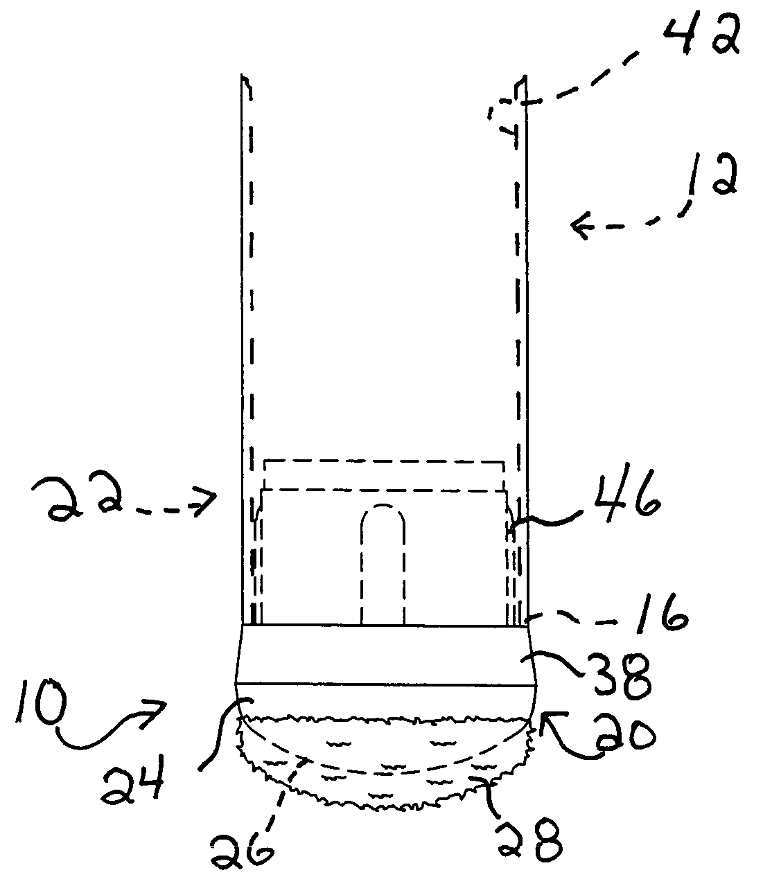
[0013]In some embodiments of the invention, the substantially elongated textile fibres prevent or reduce the generation of unpleasant sounds and vibrations when the furniture is moved and act as a protection against damage and / or dark rubber markings on a wide range of leg supporting surface textures and materials.
[0014]In some embodiments of the invention, the shape of the slider is such that the furniture glide only protrudes minimally in a radial direction relatively to the furniture leg, which reduces risks of accidental separation of the furniture glide from the furniture leg;
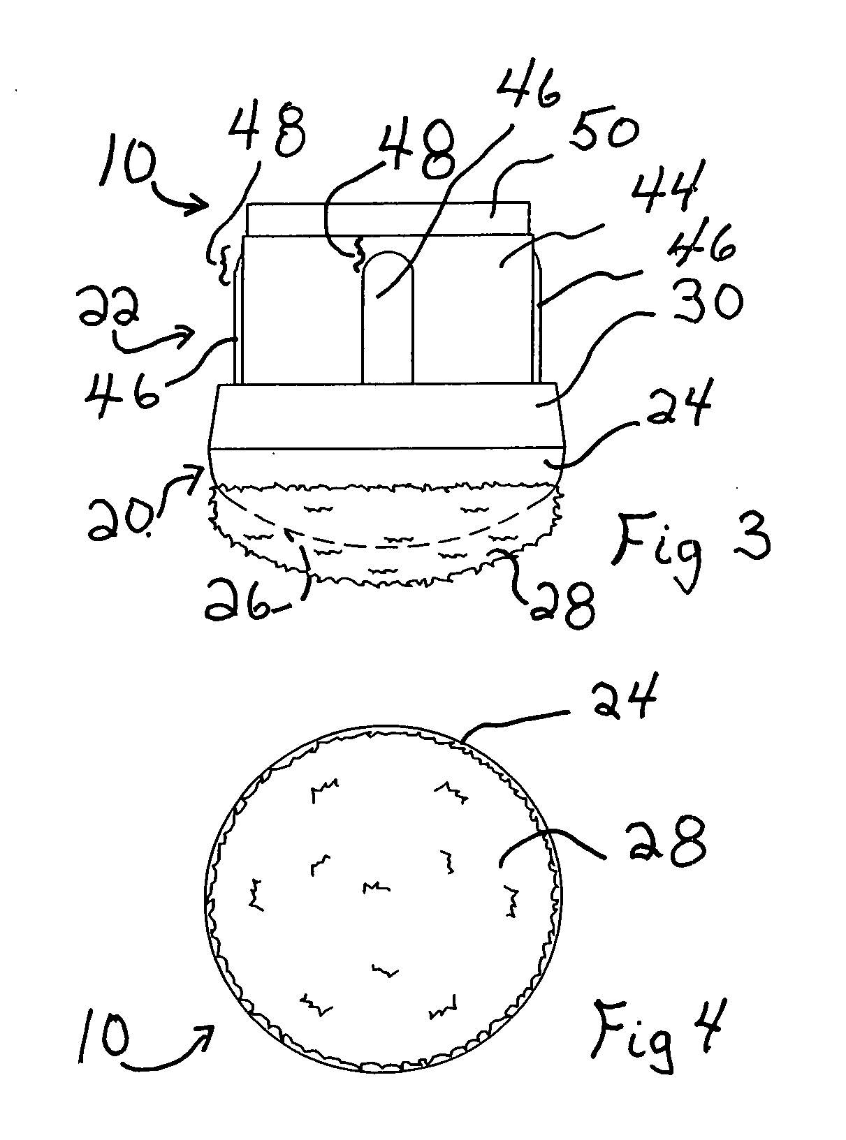
[0015]In some embodiments of the invention, the body end surface is substantially ellipsoidal cap shaped. This shape allows for the attachment of the proposed furniture glide to furniture legs that extend at various angles relatively to the leg supporting surface while keeping the above-mentioned advantages of the proposed furniture glide.

Problems solved by technology

First, in some prior art chair glides, the resilient material representing the contact surface of the chair glide with the floor, such as plastic, nylon, Teflon or rubber, can leave scratches, abrasion or dark rubber markings, particularly on shinny floors, as well as generate unpleasant noises and vibration sensations through the chair when the latter is glided around on the floor surface.
Furthermore, the undesirable dark rubber markings generally result in high cleaning costs of floors, particularly in large schools, hospitals and other public buildings.
Furthermore, the chair glide is sometimes accidentally separated from the lower end of the chair leg due to the contour of the glide that is exceeding the peripheral sidewall of the chair leg and, hence, can get caught under a shoe heel's edge and be pulled out from under the chair leg.
In these prior art chair glides, the cushioning material often ends up miss-aligned relatively to the chair leg and is relatively easily accidentally separated from the chair leg.
Yet furthermore, the resilient material representing the contact surface of the chair glide with the floor is subject to degradation and often need replacement, especially in the case of nylon caps and stick on felt pads.
Finally, some prior art chair glides have a relatively complex design and are relatively expensive to manufacture, particularly in the case of chair glides incorporating a swivel base.

Method used


Image

  • Furniture glide
  • Furniture glide
  • Furniture glide

Examples


Embodiment Construction

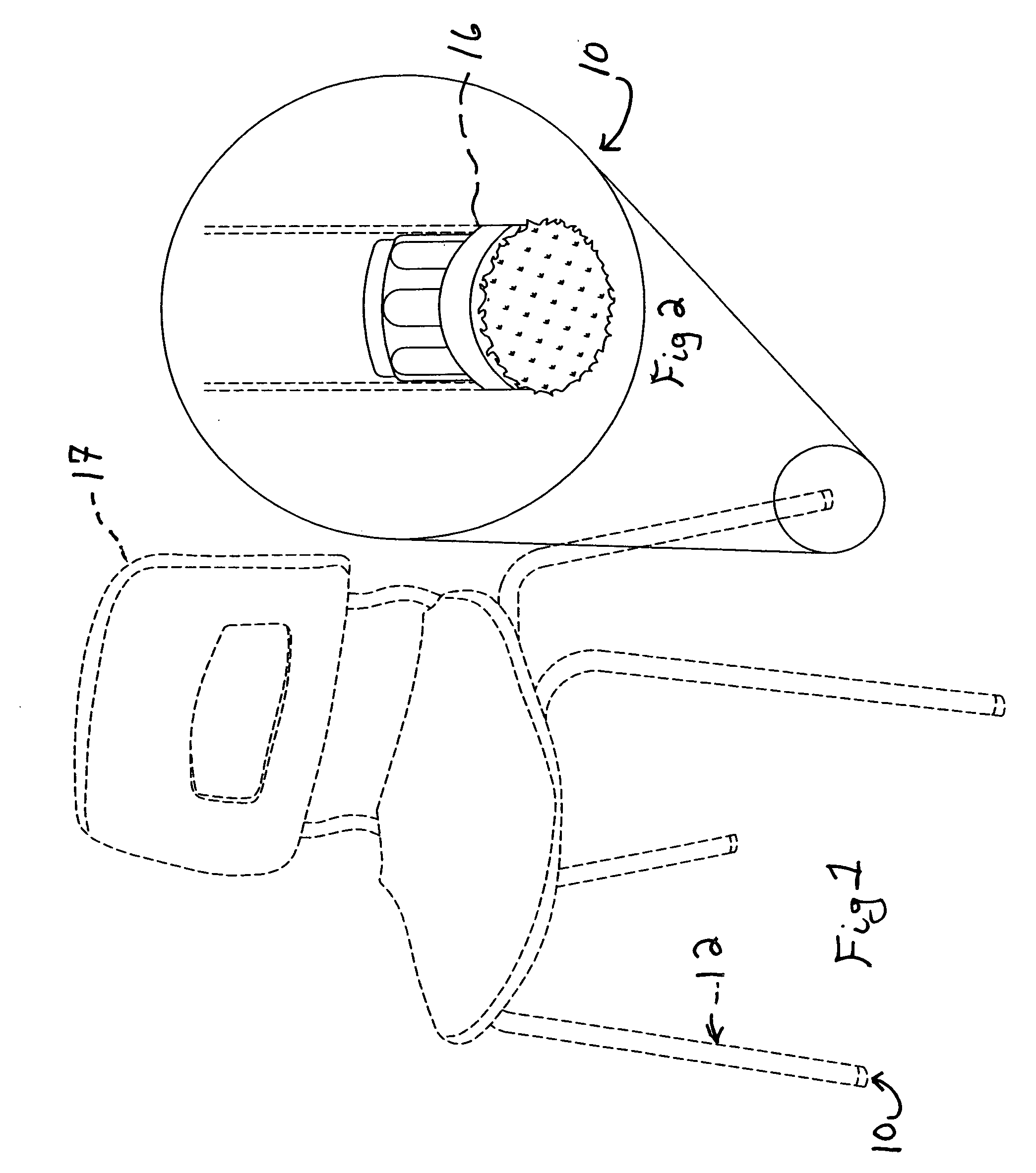
[0024]FIGS. 1 to 6 illustrate a furniture glide 10 in accordance with an embodiment of the present invention. As seen in FIGS. 1, 2, 5 and 6, the furniture glide 10 is usable for supporting a furniture leg 12 on a leg supporting surface 14 (shown in FIG. 6). Referring to FIGS. 2, 5 and 6, the furniture leg 12 defines a leg free end 16.

[0025]As shown in FIG. 1, in some embodiments of the invention, the furniture leg 12 is a leg of a chair 17. However, in other embodiments of the invention, the furniture leg 12 is a furniture leg 12 of any other suitable piece of furniture.

[0026]As seen in FIG. 1, in some embodiments of the invention, the furniture leg 12 extends in a non-perpendicular direction relatively to the leg supporting surface 14 (not seen in FIG. 1). However, in alternative embodiments of the invention, as seen in FIG. 6, the furniture leg 12 extends substantially perpendicularly to the leg supporting surface 14.

[0027]Referring to FIG. 3, the furniture glide 10 includes a sl...


PUM


Abstract

A furniture glide for supporting a furniture leg on a leg supporting surface. The furniture leg defines a leg free end. The furniture glide includes a slider, the slider including a slider body defining a body end surface. The body end surface has a substantially convex configuration. The body end surface is substantially covered with a plurality of substantially elongated textile fibres extending substantially away therefrom. A leg-to-slider attachment is operatively coupled to the slider for attaching the slider to the furniture leg substantially adjacent to the leg free end in an operative configuration in which the substantially elongated textile fibres extend substantially away from the leg free end with the body extending between the substantially elongated textile fibres and the leg free end. When the leg-to-slider attachment is attached to the furniture leg in the operative configuration and the furniture glide supports the furniture leg on the leg supporting surface, the slider defines a contact surface in which the slider abuts against the leg supporting surface. The contact surface includes a load transmitting portion in which the slider transmits load exerted onto the furniture leg to the leg supporting surface and an unloaded portion in which the substantially elongated textile fibres contact the leg supporting surface in a substantially unloaded state, the unloaded portion extending peripherally relatively to the load transmitting portion.

Description

FIELD OF THE INVENTION[0001]The present invention relates to the general field of furniture and is more particularly concerned with a furniture glide.BACKGROUND OF THE INVENTION[0002]The prior art proposes numerous glides, commonly referred to as chair glides, chair tips, glide caps, swivel glides or rubber feet, that are generally attached to the lower leg ends of conventional legged furniture such as chairs, tables, and the like.[0003]Chair glides of the prior art generally consist of a base component that can take, for example, the form of a simple end cap that extends over the lower end limit of the chair leg, an end plug having its upper portion inserted in the open lower end of a tubular chair leg, or is composed of a two part assembly separated by a pivotable link.[0004]While these chair glides of the prior art can generally fulfill the main objective of enabling a legged furniture to be easily glided around on a floor surface, they also offer one or more of the following dis...

Claims


Application Information

Patent Timeline
Patent Type & Authority Applications(United States)
IPC IPC(8): A47B91/06
CPCA47B91/12Y10T16/21A47C7/002
Inventor BERTHIAUME, GILLESBERTHIAUME, PIERRE
Owner BERTHIAUME GILLES
Learn More