
Hydraulic Jack with locking mechanism

Inactive Publication Date: 2008-07-24
WOODBURY DAVE +1
View PDF0 Cites 17 Cited by
  • Summary
  • Abstract
  • Description
  • Claims
  • Application Information

AI Technical Summary

Benefits of technology

[0010]The invention relates to a safety protection device to prevent a lifting mechanism of a jack from completely retracting in the case of a mechanical failure in the lifting mechanism or inadvertent operator error in prematurely releasing the lifting mechanism.
[0011]The invention also relates to a safety protection device that may be fitted in a floor jack having a low profile or a floor jack lacking a front axle extending across the main body of the jack.
[0012]The invention also relates to a safety device for a jack having a pawl rigidly affixed to a main body of a jack; a ratchet rigidly affixed to a lifting arm of the jack and having a plurality of teeth configured to engage the pawl, wherein raising the lifting arm of the jack causes the ratchet to travel substantially parallel to a main body of the jack and advance past the rigidly affixed pawl as the lifting arm is raised, wherein engagement of the pawl with the teeth of the ratchet positively restricts downward movement of the lifting arm when a lifting force is removed from the lifting arm.
[0013]The invention may optionally have one or more of the following: the pawl may be biased to a ratchet engaging position, the pawl may engage the ratchet at an angle of less than or equal to about 45 degrees, the pawl may be rigidly affixed approximately equidistant between the opposing walls of the main body, the pawl may be within a ratchet and pawl housing, the pawl and/or the ratchet and pawl housing may be rigidly affixed to a main body of the jack by at least one cylindrical metal rod or at least one substantially longitudinal member, the pawl may be biased to a ratchet engaging position by counter weighting the pawl and/or by use of a spring or other elastic element, a linkage connecting the pawl to a remote actuation site, a lever

Problems solved by technology

However, all hydraulic systems are subject to failure or inadvertent release resulting in an undesirable, and potentially very dangerous, retracting of the lift element.
However, this safety device suffers from the fact that the safety hook may not be sufficiently engaged to the hook up means at the time of a failure and would thereafter likely be ineffective in preventing complete retraction of the lifting means.
For example, the hook and hook-up means of the '029 patent are both pivotally mounted at opposing ends, thereby causing the hook and / or hook-up to be at a non-optimal angle relative to one another for engagement.
In addition, the hook and / or hook-up will drag on the ground beneath the jack interfering with the operators ability to position or move the jack.
Thus, when the jack is used to lift an object from a position located reasonably far from the periphery of the object, the operator will be required to approach dangerously close to the raised object to disengage the locking mechanism.
Furthermore, having the pawl pivotably connected to the lift arm may result in the force vector on the pawl being exerted at an undesirable angle relative to the ratchet or hook up means, which would result in a decreased force in the locking direction.
An additional disadvantage of the configuration described in the '029 and '966 patents is that the hook or pawl of the '029 and '966 patents must extend from the lift arm by a distance greater than the travel distance of the hydraulic piston to engage the hook-up means or ratchet.

Method used


Image

  • Hydraulic Jack with locking mechanism
  • Hydraulic Jack with locking mechanism
  • Hydraulic Jack with locking mechanism

Examples


Embodiment Construction

[0024]By way of example, the locking mechanism and release mechanism are described in view of a hydraulic floor or service jack, however, as will be recognized in view of the present specification, the present device may be adapted to other types of jacks having a lifting arm or lever as a component of the lifting mechanism.

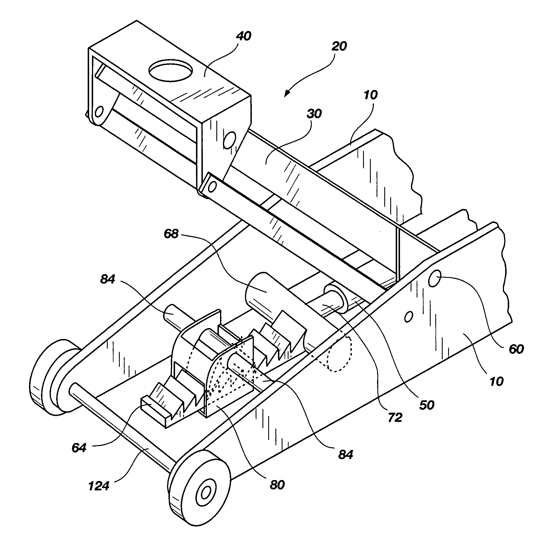
[0025]Referring to FIG. 1, the present jack comprises a main body 10, a holding mechanism 20 having a pair of lifting arms 30 connected to the main body 10, with the top end of the holding mechanism 20 having a holding portion 40 for lifting an object, and a lifting mechanism 50 for driving the lifting arms 30 upwardly about a pivot point 60 with the holding portion 40 supporting the object being lifted (for example, see, U.S. Pat. No. 4,289,299).

[0026]In the exemplary embodiment illustrated in FIG. 1, the present safety device comprises a ratchet 64 rigidly connected to a bar 68 on the end of the ram 72, where the bar 68 is then connected to the lifting arms 30 ...


PUM


Abstract

The invention relates to a safety protection device to prevent a lifting mechanism of a jack from completely retracting in the case of a mechanical failure in the lifting mechanism or inadvertent operator error in prematurely releasing the lifting mechanism. The invention also relates to a safety device release mechanism allowing the operator to disengage the safety mechanism, wherein the release mechanism is preferably mountable in a location suitably remote from the lifting mechanism, for example, the release mechanism may be detachably mounted on the handle.

Description

CROSS-REFERENCE TO RELATED APPLICATIONS[0001]This application claims the benefit of U.S. Provisional Patent Application No. 60 / 881,408, filed Jan. 19, 2007, the entirety of which is hereby incorporated by reference.TECHNICAL FIELD[0002]This invention relates to a hydraulic jack having a locking mechanism.BACKGROUND[0003]Various hydraulic floor jacks are known in the art and their use has become very common. However, all hydraulic systems are subject to failure or inadvertent release resulting in an undesirable, and potentially very dangerous, retracting of the lift element. As a result, people should not work under a vehicle or other lifted weight which is supported solely by a floor jack. Nevertheless, people frequently do work under vehicles held aloft solely by a floor jack. Therefore, it is highly desirable to prevent such floor jacks from retracting while in a raised position.[0004]Examples of hydraulic floor jacks may be found in U.S. Pat. Nos. 1,767,124; 1,784,116; 1,978,451;...

Claims


Application Information

Patent Timeline
IPC IPC(8): B66F5/04
CPCB66F5/04
Inventor WOODBURY, DAVEOTTERSTOM, JOE
Owner WOODBURY DAVE
Learn More