
Aviation vision apparatus

a vision apparatus and aircraft technology, applied in the field of aircraft vision systems, can solve the problems of impracticality for use with general aviation aircraft, high cost of such systems, and affecting the image quality, so as to enhance the pilot's ability to fly an aircraft, enhance the vision, and increase the visibility

Active Publication Date: 2008-07-24
ELBIT SYSTEMS OF AMERICA LLC
View PDF2 Cites 18 Cited by
  • Summary
  • Abstract
  • Description
  • Claims
  • Application Information

AI Technical Summary

Benefits of technology

The invention is an aviation vision apparatus that helps enhance a pilot's ability to fly an aircraft by providing increased visibility. It uses a focal plane array based on microbolometers and a non-uniformity correction ability to adjust the vision scene. The apparatus is a single line replaceable unit that can be mounted on the top or bottom of an aircraft and can be easily boresighted using shims. It is light weight, weighing less than five pounds overall, and is completely enclosed in aerodynamic fairing that permits installation like an antenna on the aircraft.

Problems solved by technology

The optics exterior surface can drop below dew point during operation, impeding image quality due to condensation and frost.
Further, the high cost of such systems makes them impractical for use with general aviation aircraft.

Method used


Image

  • Aviation vision apparatus
  • Aviation vision apparatus
  • Aviation vision apparatus

Examples


Embodiment Construction

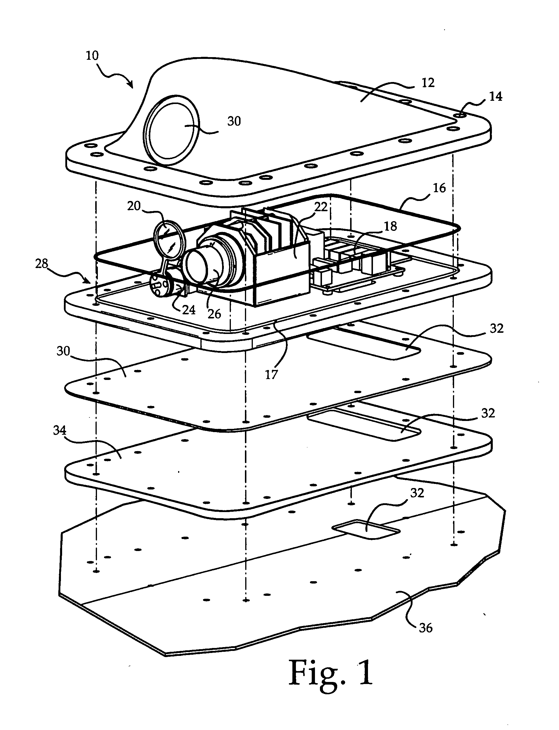
[0028]FIG. 1 is an isometric exploded view of the invention 10 showing the major components. Cover 12 is aerodynamically fairing-shaped. Cover 12 mates to base plate 28. Eleven aircraft grade screws, 14, secure cover 12 to base plate 28 along with O-ring 16 thereby completes sealing invention 10. O-ring 16 is preferentially made from a material that can withstand high temperatures and pressures. O-ring 16 is fitted into circumferential slot 17, thus effectively sealing cover 12 to base plate 28. Optical base plate 28 is designed to be bolted to the outer shell of an aircraft without deformation so that the critical lens assembly is not affected while maintaining a seal pressurized interior which is subjected to +70 C to −54 C temperatures.

[0029]An ABS plastic shim 34 simulates the complex spherical top surface 36 of the aircraft so that unit 10 can be mounted in various locations on the aircraft such as behind or below the windscreen or on the bottom of the fuselage. Rubber gasket 3...


PUM


Abstract

An aviation vision apparatus. Its purpose assists a pilot's ability to fly an aircraft by providing increased visibility. The apparatus features an uncooled IR sensor for vision enhancement. An integrated window assembly is provided which permits the sensor to obtain its imagery. The apparatus also has an integrated aerodynamic enclosure. The apparatus features electronics responsible for window assembly window control functions and IR sensor control. The apparatus is a single line replaceable unit that receives control commands from the aircraft's head-down display or other control modules. The unit also provides for the video display.

Description

[0001]This application claims benefit of U.S. Provisional Application Ser. No. 60 / 734,816 filed Nov. 9, 2005, pursuant to 35 USC § 119(e).FIELD OF THE INVENTION[0002]This invention relates to vision systems for aircraft, in particular, an apparatus to help enhance a general aviation pilot's ability to fly by increasing visibility.BACKGROUND OF THE INVENTION[0003]It is well known that assisting an aircraft pilot with maneuvers in situations of low or no visibility is desirable and numerous solutions have been provided to accomplish that task. Typically, modern aircraft can be equipped with Forward Looking Infrared Cameras (FLIR). These cameras are part of the Enhanced Vision System (EVS), which is used to improve the capability for commercial, business and military aircraft to execute precision approaches and land safely in fog, rain, snow and other reduced visibility conditions thereby reducing accidents. The EVS also provides improved awareness during ground operation aiding in the...

Claims


Application Information

Patent Timeline
Patent Type & Authority Applications(United States)
IPC IPC(8): H01L25/00
CPCB60R11/04H04N5/3656H04N5/33H04N25/674H04N23/20
Inventor EVERETT, JONATHANGAGNON, JOHN A.PASHOS, ATHANASIOSRODRIGUEZ, ROBERTOWOLFE, RICHARD
Owner ELBIT SYSTEMS OF AMERICA LLC
Learn More