
Method and apparatus for forming undulating conduit

a conduit and undulating technology, applied in the direction of rigid pipes, flow mixers, mixers, etc., can solve the problems of unfavorable flow properties, apparatus and methodology are not likely to be practical for large-diameter conduits or pipes made of certain materials, and the flow properties are not desirabl

Inactive Publication Date: 2008-07-24
UNDULTEC
View PDF8 Cites 43 Cited by
  • Summary
  • Abstract
  • Description
  • Claims
  • Application Information

AI Technical Summary

Benefits of technology

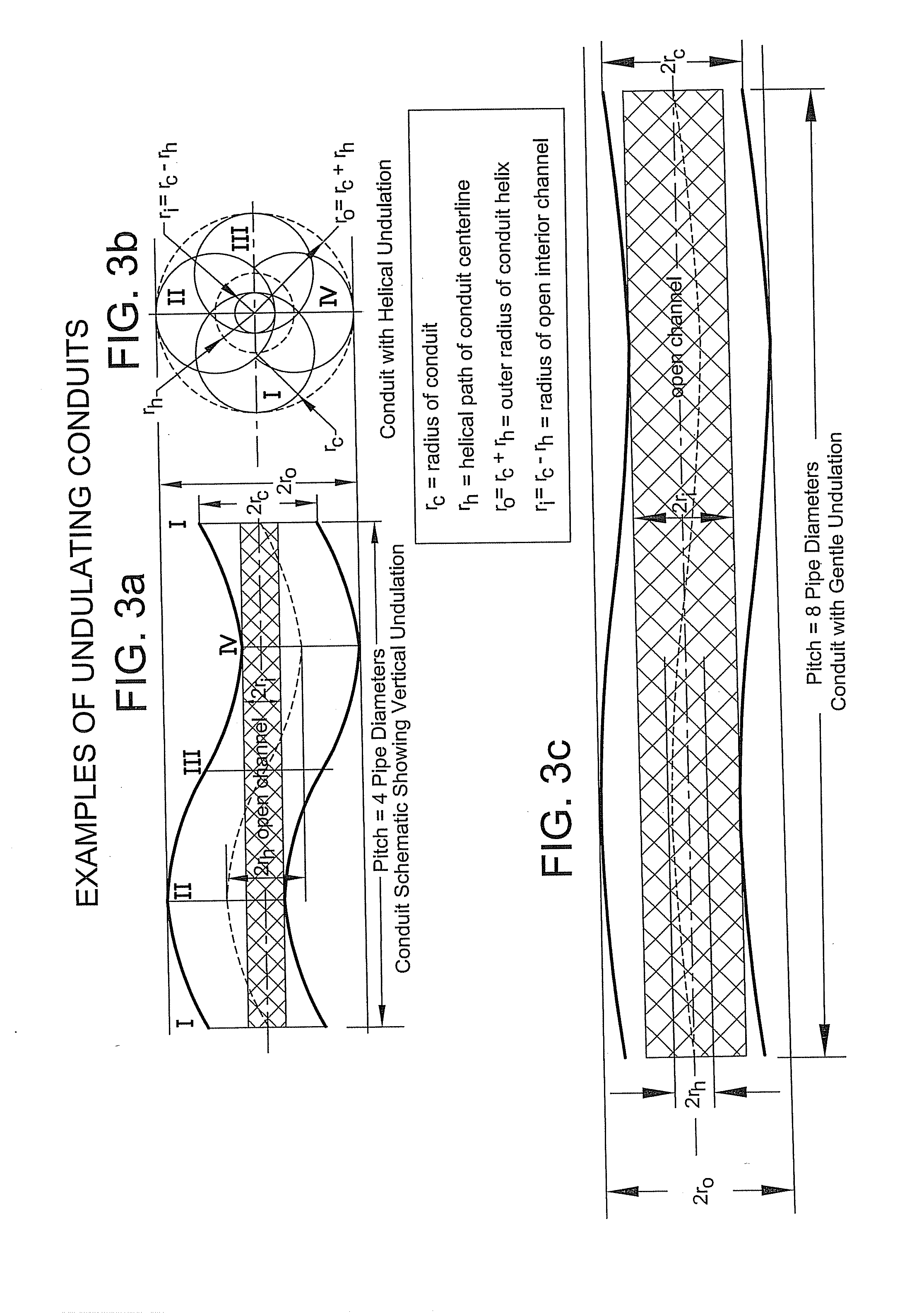
[0009]The undulating pipe may be a hydrodynamic static mixing apparatus having a preselected and predetermined configuration and length for mixing and/or transporting various substances, including fluids and solids contained in slurries, said pipe having an interior forming a helical coil having a pitch and with the diameter of the interior being greater than a coil helix diameter, said pipe including a generally round internal cross-section havin...

Problems solved by technology

However, such apparatus and methodology creates ridges and valleys in the interior of the pipe, which when formed as shown in the reference, can produce undesirable flow properties for fluid passing through the pipe.
Furthermore, such apparatus and methodology would not likely be practical for large-diameter conduits or for pipes made of certain materials.

Method used


Image

  • Method and apparatus for forming undulating conduit
  • Method and apparatus for forming undulating conduit
  • Method and apparatus for forming undulating conduit

Examples


Embodiment Construction

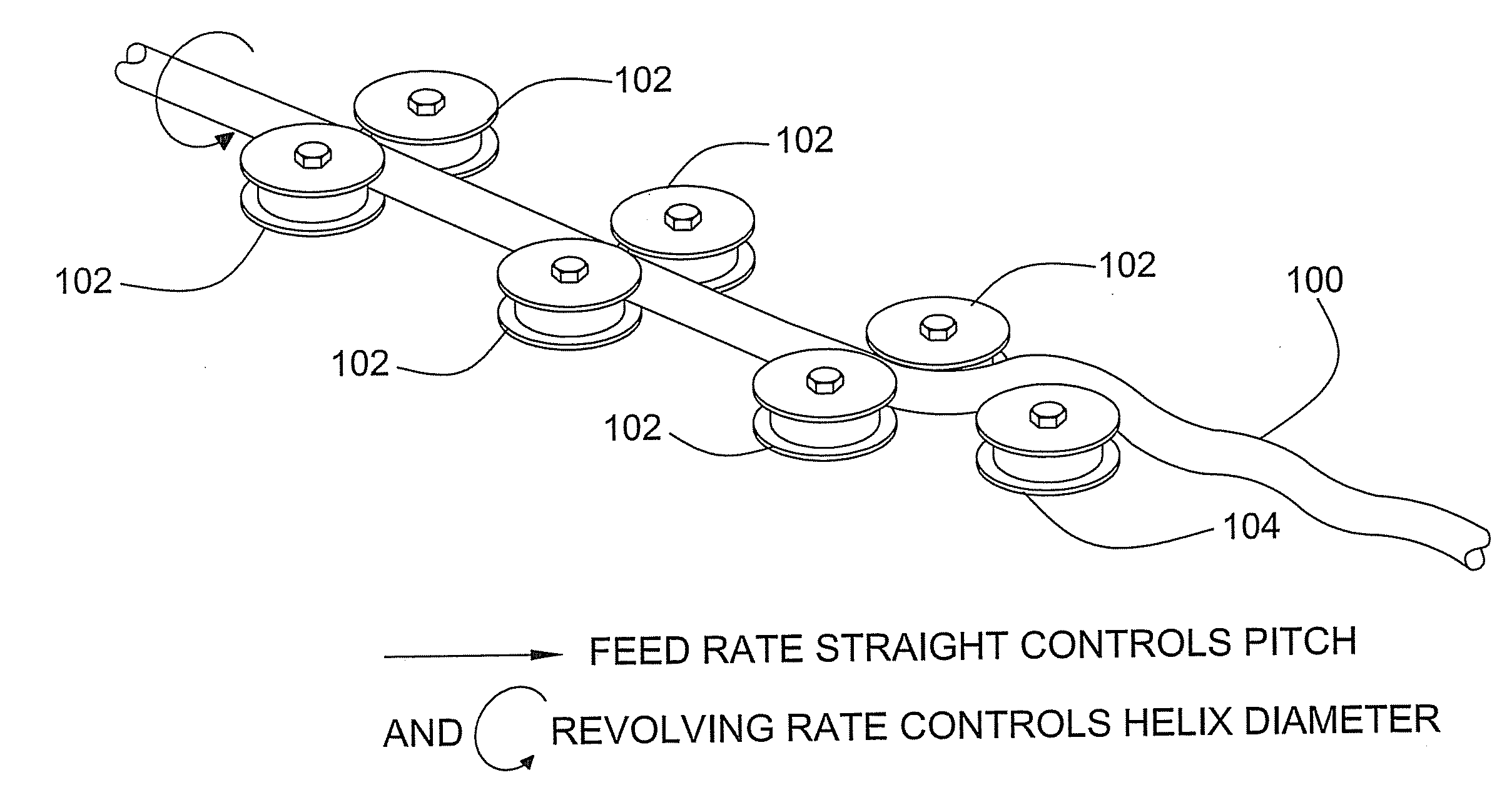
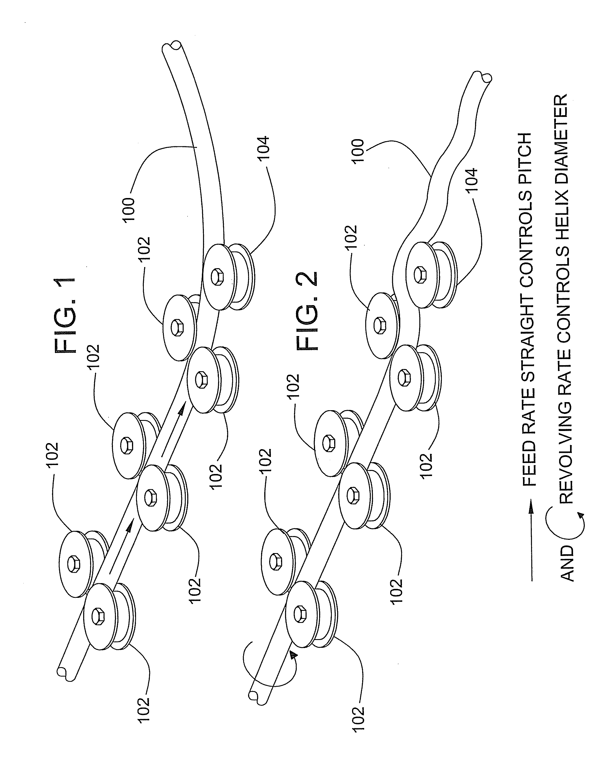
[0024]The invention provides a method and apparatus for forming an undulating pipe having a helical interior path. A pipe of this kind may be used for the transmission of fluids or slurries. The helical undulating shape may help to transmit slurries in such a manner that solids disposed within the fluid may travel in a suspended state to limit the amount of solid material that may collect near the bottom of the pipe.

[0025]For example, in the application of oil field drilling, it is common that the oil slurry removed from the earth would contain a mixture of liquid and solid particles, such as oil sands. This mixture is commonly transported from the drilling site to a remote location for separation of the slurry. In straight pipes, the solid material in the slurry tends to collect near the bottom of the pipe, thus obstructing transport. In pipes having undulation in a single plane, the solid material tends to collect in the valleys of the undulating pipe and the abrasiveness of the s...


PUM

PropertyMeasurementUnit
Diameteraaaaaaaaaa
Lengthaaaaaaaaaa
Radiusaaaaaaaaaa

Abstract

Method and apparatus for forming conduit or pipe of various sizes into undulating, helical pipe by feeding a length of conduit at a controlled rate through a bending mechanism while also continuously rotating the pipe at a controlled rate so that bending occurs in multiple axis directions and the diameter of the helical path of the conduit centerline of the coil is less than the conduit diameter, the pitch is greater than the pipe diameter, and a straight open channel is retained through the pipe coil.

Description

CROSS-REFERENCE TO RELATED APPLICATIONS[0001]This patent application claims the benefit of U.S. Provisional Patent Application No. 60 / 874,848, filed Dec. 14, 2006, which is incorporated by reference in its entirety herein.FIELD OF THE INVENTION[0002]This invention pertains to a method and apparatus for forming bent conduit or pipe of various sizes that can be used for a variety of applications, including but not limited to hydrodynamic mixing with no moving parts, generally known in the industry as a static mixer. This invention provides a method and apparatus which can be utilized to form the undulating conduit disclosed and claimed in my below mentioned applications and U.S. Pat. No. 6,896,007, which is highly effective for extraction of oil from oil sands deposits present in many countries throughout the world.BACKGROUND OF THE INVENTION[0003]Various methods and apparatus are employed to bend or form lengths of pipe. In U.S. Pat. No. 4,317,353, an automated apparatus is shown for...

Claims


Application Information

Patent Timeline
IPC IPC(8): B01F13/00B21D9/04
CPCB01F5/0646B01F5/0647B21D11/07B21D7/08B01F5/065B01F25/4333B01F25/4331B01F25/433
Inventor CYMBALISTY, LUBOMYR M.HEMPHILL, FREDERICK ARTHUR
Owner UNDULTEC
Learn More