
Management of protection path bandwidth and changing of path bandwidth

a technology of path bandwidth and protection path, applied in the field of management of protection path bandwidth and changing path bandwidth, can solve the problems of waste of bandwidth, inflexible allocation of bandwidth, and fixed preallocation of protection path bandwidth, and achieve the effect of efficient use of limited resources

Inactive Publication Date: 2008-07-17
FUJITSU LTD
View PDF14 Cites 18 Cited by
  • Summary
  • Abstract
  • Description
  • Claims
  • Application Information

AI Technical Summary

Benefits of technology

[0016]It is an object of the present invention to provide a method of protection path bandwidth management that can efficiently use limited resources.

Problems solved by technology

However, since every path is not necessarily a path that must be backed up by a protection path to maintain its quality of service, fixedly preallocating the protection path bandwidth would be wasteful of the bandwidth.
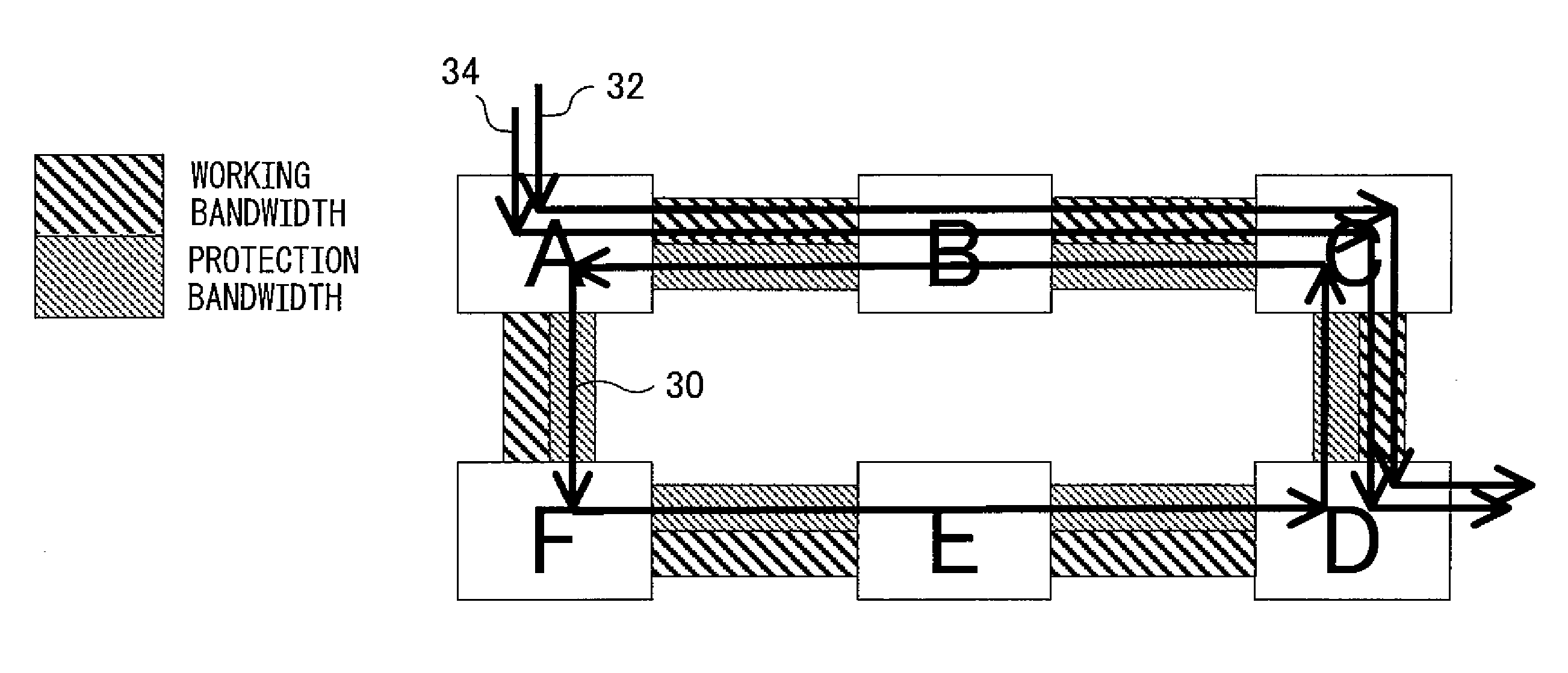
Further, when two protection paths, each set up in a loop, share the same link portion, if the bandwidth of each protection path is fixedly preallocated for the shared link portion, there arises the problem that the bandwidth cannot be allocated flexibly, i.e., even when the total bandwidth of the paths protected by one of the loop protection paths is small, the bandwidth of the other loop protection path cannot be increased to increase the bandwidth of the paths that can be protected by that other loop protection path.

Method used


Image

  • Management of protection path bandwidth and changing of path bandwidth
  • Management of protection path bandwidth and changing of path bandwidth
  • Management of protection path bandwidth and changing of path bandwidth

Examples


first embodiment

[0049]FIG. 10 shows a flowchart illustrating the processing performed at each node upon reception of a message in the present invention. In FIG. 10, first the message type of the received message is checked (step 1000); if the received message is the protection path bandwidth change request message, available bandwidth for the protection path is checked (step 1002). If the bandwidth available for the protection path is not sufficient, the following processing is not performed. Next, if the received message is the bandwidth change request message that has been generated by the receiving node itself, the protection path bandwidth change response message is generated and transferred upstream along the protection path (step 1004). Otherwise, the received message is transferred downstream along the protection path (step 1006).

[0050]If the received message is the protection path bandwidth change response message, the bandwidth of the protection path is changed (step 1008), and if the rece...

second embodiment

[0056]FIGS. 12 to 14 shows a bandwidth changing procedure according to the present invention. As in the foregoing embodiment, in response to the setup request for the working path 1, the working path 1 is set up and, at the same time, the protection loop is set up in a loop. In FIG. 12, when the node B that received the PATH message for the working path 2 determines that the bandwidth of the protection path needs to be changed, the node B transfers the bandwidth change request message containing the path identifier of the protection path and the requested bandwidth (30 Mbps) in the downstream direction along the protection path toward the node A which is the endpoint of the protection path. If there is some other node between the node B and the node A at the endpoint of the protection path (though there is no such other node in the illustrated example), such other node checks whether the bandwidth can be changed in accordance with the bandwidth change request, and transfers the mess...


PUM


Abstract

A highly efficient protection path bandwidth management method is provided. When a protection path is set up in a loop with a node A as the starting point and endpoint in order to protect a working path, the bandwidth of the protection path is changed by transferring a bandwidth change request message, containing the identifier of the protection path as well as the value of the bandwidth after the change, so as to cycle once around the protection path set up in a loop starting from a node B that first received a PATH message for a working path.

Description

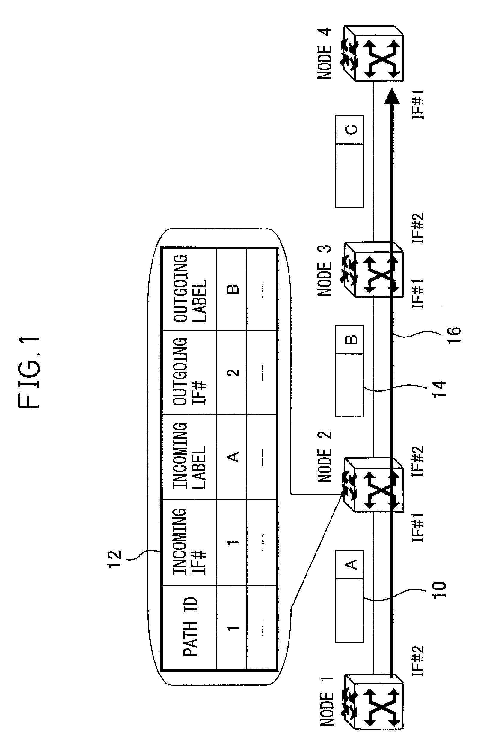
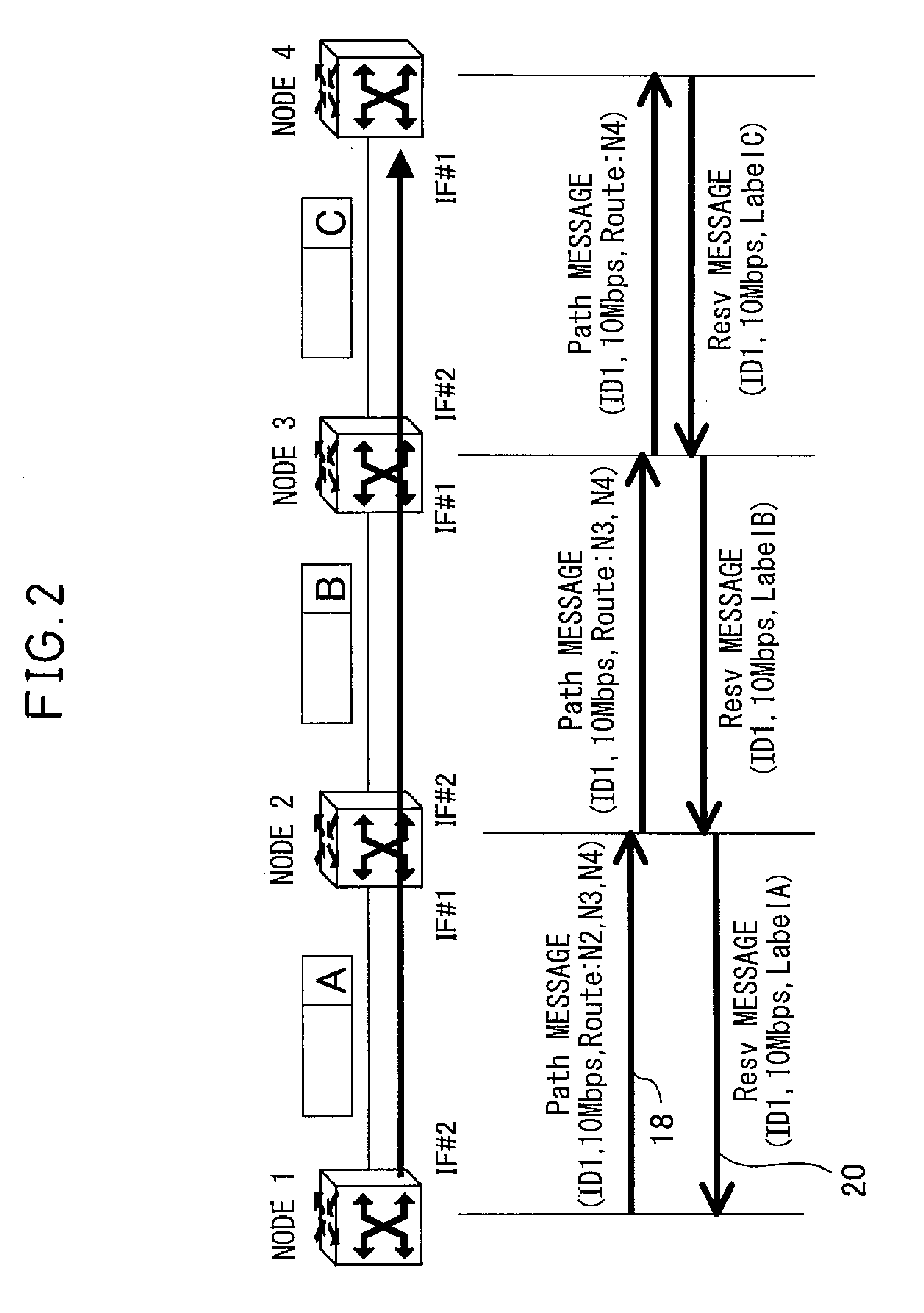
BACKGROUND OF THE INVENTION[0001]1. Field of the Invention[0002]The present invention relates to a method for managing protection path bandwidth when using a protection path set up in a loop to recover from a failure occurring in at least a portion of a path, and a method for changing the path bandwidth, and more particularly to a method for managing protection path bandwidth in an MPLS (Multi-Protocol Label Switching) network and a method for changing the bandwidth.[0003]2. Description of the Related Art[0004]To transfer packets such as IP (Internet Protocol) packets at high speed, there has been developed a technology known as MPLS (Multiprotocol Label Switching) in which a short fixed-length label is attached at the head of each packet in addition to the header information contained therein and the packet is transferred using the thus attached label.[0005]Each node maintains a label table which shows incoming interface numbers, outgoing labels corresponding to incoming labels, an...

Claims


Application Information

Patent Timeline
IPC IPC(8): G06F11/07H04L12/42H04L12/437H04L45/24H04L45/247
CPCH04L41/0896H04L45/50H04L45/28H04L45/22
Inventor KANO, SHINYA
Owner FUJITSU LTD
Learn More