
Thermal signature target form

a technology of thermal signature and target form, which is applied in the direction of heat exchange equipment, metal-working equipment, weapons, etc., can solve the problems of not being competitive in the thermal target market, screen printed ink matrix technology lacks a sturdy, durable form, and is unsuitable for repeated projectile impact during live-fire training exercises

Inactive Publication Date: 2008-07-17
FATS INC
View PDF14 Cites 11 Cited by
  • Summary
  • Abstract
  • Description
  • Claims
  • Application Information

AI Technical Summary

Problems solved by technology

Initial analysis of this matrix technology showed that it may not be competitive in the thermal target market.
Further, the screen printed ink matrix technology lacks a sturdy, durable form rendering it unsuitable to repeated projectile impacts during live-fire training exercises.
This requires extra setup and breakdown time and negatively impacts usability considerations.
Finally, the two-dimensional target is not lifelike and thus presents a less than realistic target for training purposes.
Foils and films lack durability and can be damaged or destroyed by foul weather or when struck by projectiles during a live-fire exercise.
Blanket modules are mechanically secured to an existing target panel or form using tape, staples, or other manual fastening means, a time-consuming process that also decreases the uniformity of the targets.
Further, during live-fire exercises, loosely attached blanket modules can move, deform, or become unattached after being struck by multiple bullets or other projectiles.
This can cause a degradation in the thermal signature of the target, forming patchy or otherwise distorted thermal signatures.
Such an insulating adhesive renders the device difficult to transport on and off a military training ground since the device tends to adhere to surfaces that it contacts.
In addition, the device emits a very large amount of heat, consuming copious amounts of energy and also rendering it unsuitable for simulating targets with lower amounts of emitted IR radiation.
Finally, the floor heating system cannot be readily molded to form realistic three-dimensional shapes.

Method used


Image

  • Thermal signature target form
  • Thermal signature target form
  • Thermal signature target form

Examples


Embodiment Construction

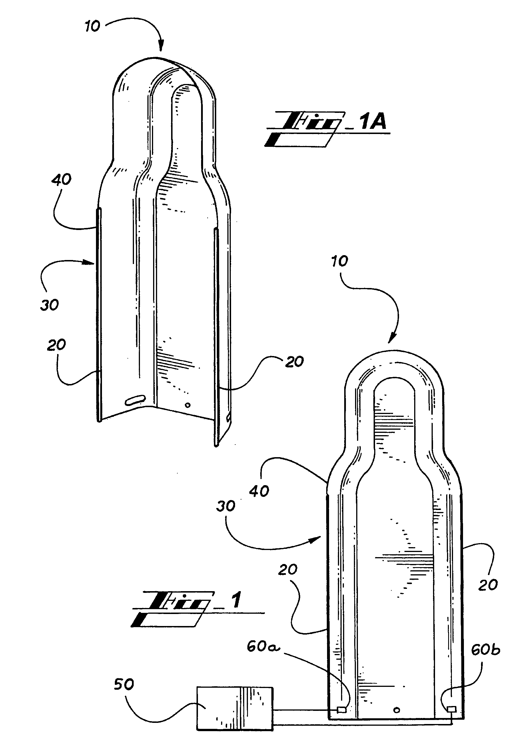
[0017]With reference to FIG. 1 and FIGS. 1a-1d, a molded thermal signature target form 10 in accordance with an embodiment of the invention is illustrated. A thermal signature target form 10 comprises a conductive polymer material suitable for conducting infrared (IR) radiation such that a thermal signature is created and viewable by any number of suitable IR imaging or viewing systems. A pair of busbars 20 are embedded or attached to the outside edge 30 of the thermal signature target form 10, and the busbars 20 direct electrical current throughout the entire target form 10. When the thermal signature target form 10 is electrically energized, the resistance of the conductive polymer material creates heat, causing the target form 10 to emit infrared (IR) radiation which can be detected using suitable IR imaging or viewing systems. The busbars 20 can be attached to the thermal signature target form 10 by pre-molding grooves 40 into the target form 10 and embedding the busbars 20 in t...


PUM

PropertyMeasurementUnit
Fractionaaaaaaaaaa
Poweraaaaaaaaaa
Shapeaaaaaaaaaa

Abstract

A three-dimensional molded thermal signature target form comprising a conductive polymer material suitable for conducting infrared radiation such that a thermal signature is created and viewable by any number of suitable IR imaging or viewing systems. The thermal signature target form includes embedded busbars attached to a power source. The thermal signature target form can provide a realistic, inexpensive and safe live-fire target for training in thermal image recognition and shooting.

Description

RELATED APPLICATION[0001]This application claims the benefit of priority of U.S. provisional application Ser. No. 60-885,266, filed Jan. 17, 2007, which is relied on and incorporated herein by reference.FIELD OF THE INVENTION[0002]The invention relates generally to a thermal signature target form.BACKGROUND OF THE INVENTION[0003]Today's military and police forces train with modern weapons systems requiring live-fire targets which accurately simulate the thermal signature of battlefield threats. At this time, there are a number of thermal signature simulation technologies which can be added to or act upon a conventional target panel or form. In general, these technologies require that separate thermal simulation elements be added to an existing target panel or form. Military or police organizations have a need for a high-performance, low-cost thermal target for use during live-fire training exercises.[0004]A number of existing technologies have been reviewed to determine their manufa...

Claims


Application Information

Patent Timeline
IPC IPC(8): F41J2/00
CPCF41J2/02Y10T29/4935F41J7/06F41J7/04
Inventor HETLAND, JONATHAN MARK
Owner FATS INC
Learn More