Eureka AIR delivers breakthrough ideas for toughest innovation challenges, trusted by R&D personnel around the world.

Method of manufacturing a catalyst

a manufacturing method and catalyst technology, applied in the direction of catalyst activation/preparation, metal/metal-oxide/metal-hydroxide catalysts, moulding machines, etc., can solve the problem of particular but not exclusively suitable methods

Inactive Publication Date: 2008-07-10
SHELL OIL CO
View PDF8 Cites 23 Cited by
  • Summary
  • Abstract
  • Description
  • Claims
  • Application Information

AI Technical Summary

Benefits of technology

The present invention provides a method for manufacturing a catalyst, catalyst precursor, or catalyst support by mixing a refractory metal oxide or precursor with a liquid and optionally a catalytically active component or precursor to form a paste. The paste is then extruded through a die with one or more apertures to form catalyst support extrudates. The invention is characterized by the use of an extruder with a die plate comprising one or more dies, each die having a plurality of apertures, with the outlet of each aperture having a cross sectional area of 6 mm2 or less, preferably 4 mm2 or less, especially 2.2 mm2 or less. The invention also involves the use of an extruder with at least one die wherein the combined cross sectional area of all apertures at the inlet of the apertures relative to the total cross sectional area of the die at the inlet is higher than 50%, preferably more than 70%, especially more than 80%.

Problems solved by technology

The method is particularly but not exclusively suitable in a process for manufacturing a catalyst, catalyst precursor, or a catalyst support for use in a Fischer-Tropsch process.

Method used


Image

  • Method of manufacturing a catalyst
  • Method of manufacturing a catalyst
  • Method of manufacturing a catalyst

Examples


example 1

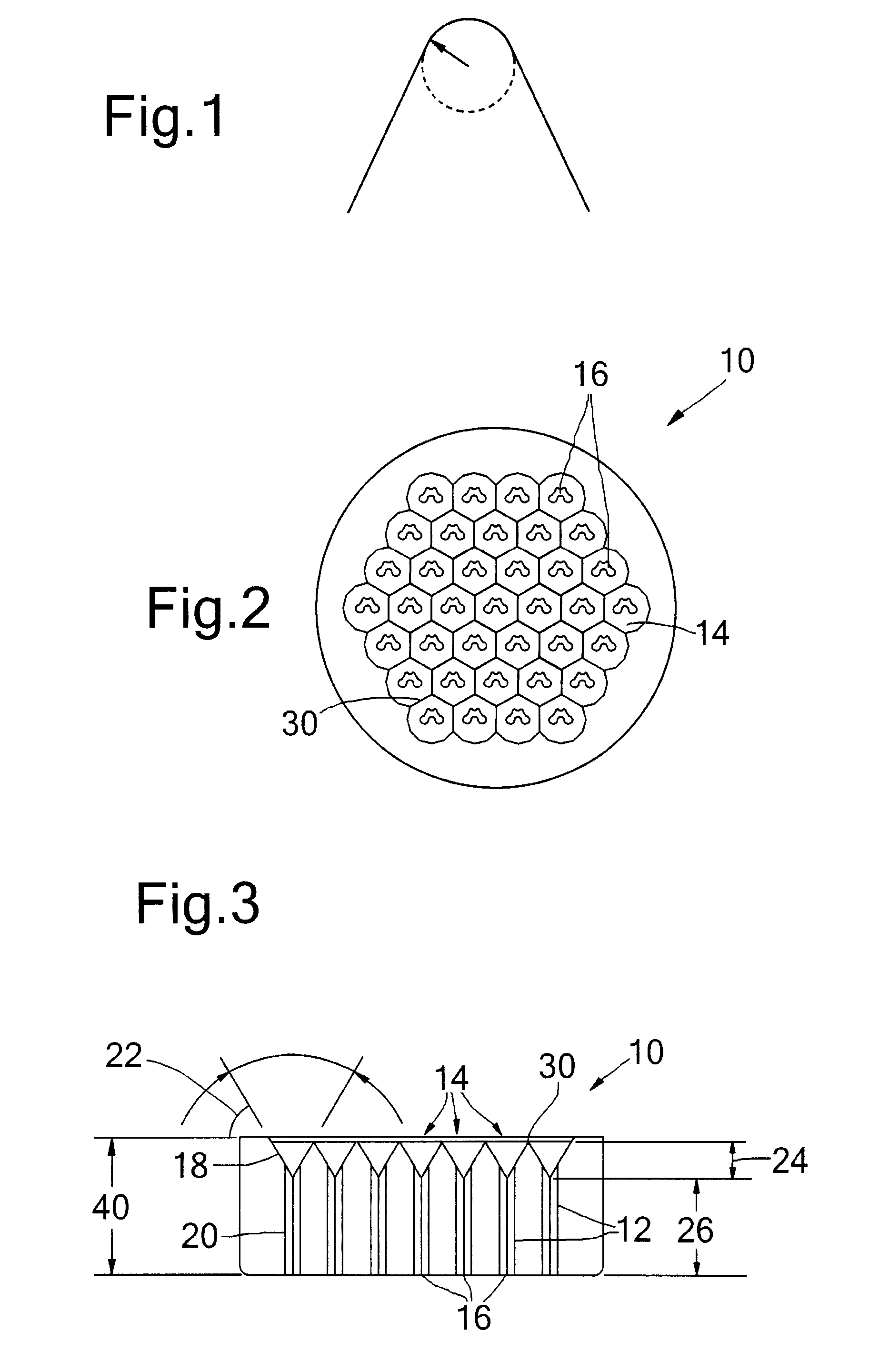
[0113]Embodiments of the present invention will now be described, by way of example only, with reference to the accompanying figures.

[0114]A die 10 is shown in FIGS. 2 & 3 and comprises a series of apertures 12 extending though the die from a first side to a second, opposite side. The die 10 may be provided in an outlet end of an extruder (not shown). Many such dies may be provided in a die plate connected to an extruder head of the extruder. In one embodiment there are twenty four such dies.

[0115]In accordance with the present invention, the apertures have an inlet 14 of a greater cross-sectional area than the outlet 16, as shown in FIGS. 2 and 3. Between the apertures at the inlet are rims 30. Each aperture comprises a cone-shaped portion 18 and a channel portion 20. The cone-shaped portions 18 increase the diameter of the inlets 14 of the apertures such that they are larger than the outlets 16. The length 24 of the cone-shaped portion may be around 3 mm and the length 26 of the c...

example 2

[0120]A clay-like paste was prepared containing titania, a cobalt and manganese source (cobalt / manganese co precipitated hydroxide) poly vinyl alcohol, citric acid and water.

[0121]In a first experiment, a portion of this paste was added to an extruder comprising, at the end thereof, four known dies with non-tapered apertures. The outlet of the apertures in the dies were of the CA-shape.

[0122]In a second experiment, another portion of the paste was added to an extruder comprising, at the end thereof, four dies in accordance with the present invention. The apertures had an inwardly tapered opening and a channel, the channel inlet and outlet having a substantially equal cross sectional area. The outlet of the apertures in the dies were of the CA-shape.

[0123]The extrudate production rate for the first portion of paste was found to be 10.8 kg / h. The extrudate production rate for the second portion of paste was found to be 18.3 kg / h. Thus a significant increase in production rate was foun...


PUM

PropertyMeasurementUnit
cross sectional areaaaaaaaaaaa
radiusaaaaaaaaaa
cross sectional areaaaaaaaaaaa

Abstract

A method of manufacturing a catalyst, a catalyst precursor, or a catalyst support comprising: (a) mixing a refractory metal oxide or precursor thereof with a liquid to form a paste; (b) adding said paste to an extruder, the extruder having a die plate comprising one or more dies, each die having a plurality of apertures, the outlet of each aperture having a cross sectional area of 6 mm2 or less; (c) extruding the paste through the apertures to form catalyst support extrudates;wherein the inlet of the apertures has a greater cross sectional area than the outlet of said apertures; and wherein for at least one die the combined cross sectional area of all apertures at the inlet relative to the total cross sectional area of the die at the inlet is higher than 50%.

Description

[0001]This application claims the benefit of European Application No. 06123098.3 filed Oct. 27, 2006 which is incorporated herein by reference.BACKGROUND[0002]The present invention relates to a method of, and a die for, extruding a catalyst, a catalyst precursor, or a catalyst support. The method is suitable in a process for manufacturing a catalyst, catalyst precursor, or a catalyst support for use in a multitubular fixed bed reactor. The method is particularly but not exclusively suitable in a process for manufacturing a catalyst, catalyst precursor, or a catalyst support for use in a Fischer-Tropsch process.[0003]The Fischer-Tropsch process can be used for the conversion of synthesis gas (from hydrocarbonaceous feed stocks) into liquid and / or solid hydrocarbons. Generally, the feed stock (e.g. natural gas, associated gas and / or coal-bed methane, heavy and / or residual oil fractions, coal, biomass) is converted in a first step into a mixture of hydrogen and carbon monoxide (this mi...

Claims


Application Information

Patent Timeline
Patent Type & Authority Applications(United States)
IPC IPC(8): B01J23/00B29C33/44B29C47/12B01J35/00B29C48/11B29C48/12B29C48/30
CPCB01J23/8892B01J35/023B01J35/026B01J37/0009B22F2998/00B28B3/269C10G2/33B29C47/0028B29C47/12B29L2031/60B22F3/225Y10S502/514B29C48/11B29C48/12B01J35/50B01J35/40
Inventor VAN DEN BRINK, PETER JOHNDOGTEROM, RONALD JANMESTERS, CAROLUS MATTHIAS ANNA MARIA
Owner SHELL OIL CO
Why Eureka
Eureka Blog
Learn More