
Wire headset with integrated switch

a wired headset and switch technology, applied in the field of headsets, can solve the problems of bulkyness and limited control functions

Active Publication Date: 2008-07-10
APPLE INC
View PDF7 Cites 84 Cited by
  • Summary
  • Abstract
  • Description
  • Claims
  • Application Information

AI Technical Summary

Benefits of technology

[0005]Switches that can be incorporated in wires, that can feature small and unobtrusive profiles, and that can control one or more functions of devices coupled to the wires, are provided. Switches that can be easy to use without requiring users to look at the switches are also provided.
[0007]Incorporating the switch within the switch housing advantageously can eliminate the need to provide a discrete switch member that is visible (e.g., that protrudes from the housing), thus providing a more aesthetically pleasing housing with switch functionality. In addition, the relative ease in activating the switch in accordance with embodiments of the invention may be greater than that of peripheral assemblies (e.g., headsets) having discrete switch members because there may be no need to discern where the switch is located in order to activate the switch. The user can merely squeeze the housing of the integrated switch assembly to activate the switch.
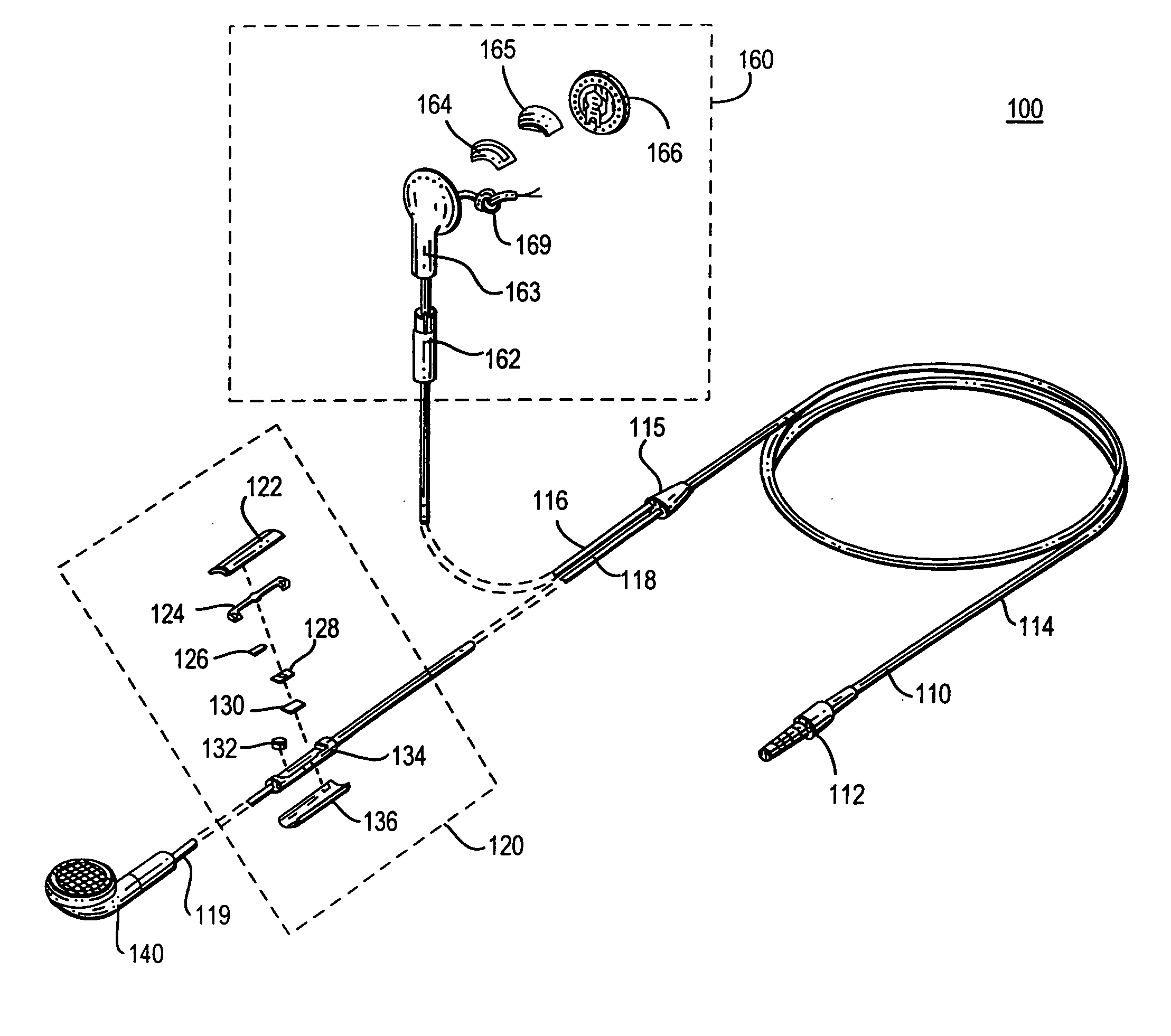
[0009]In certain headset embodiments, for example, having a single peripheral assembly (e.g., a monaural headphone having a single speaker or earbud), the integrated switch assembly may be placed along the cord assembly relatively near that single peripheral assembly. In certain other headset embodiments having two or more peripheral assemblies (e.g., stereo headphones having left and right speakers or earbuds), the integrated switch assembly may be generally associated with and placed along the cord assembly in relative proximity to one or the other peripheral assembly. For example, when the peripheral assembly is placed in a position of its intended use (e.g., placed in or near the ear or ears of the user), the integrated switch assembly can be positioned along the cord assembly such that the user can relatively easily locate the switch housing (as opposed to having the user fumble around for a switch located far away from the peripheral assembly).
[0012]The integrated switch assembly can include cord assembly fasteners or crimps that securely fix the switch assembly to the cord assembly. For example, a first fastener can secure a plug portion of the cord assembly and a second fastener can secure a peripheral portion of the cord assembly. Wires of the cord assembly (e.g., positive and ground wires) can be routed through the switch assembly without interfering with the switch, and in some embodiments the microphone. In addition, the fasteners can be located within the switch housing, thereby making the cord assembly appear integrated with the switch housing. This can provide an aesthetically pleasing appearance and also can make the switch assembly appear as a relatively non-descript and seamless extension of the cord assembly.

Problems solved by technology

A drawback of such switches that have been implemented in headset wires is that they tend to be bulky and have limited control functions.

Method used


Image

  • Wire headset with integrated switch
  • Wire headset with integrated switch
  • Wire headset with integrated switch

Examples


Embodiment Construction

[0013]Switches are provided that can be incorporated in wires to have small and unobtrusive profiles, and that can control one or more functions of devices coupled to the wires, and are described below with reference to FIGS. 1-10.

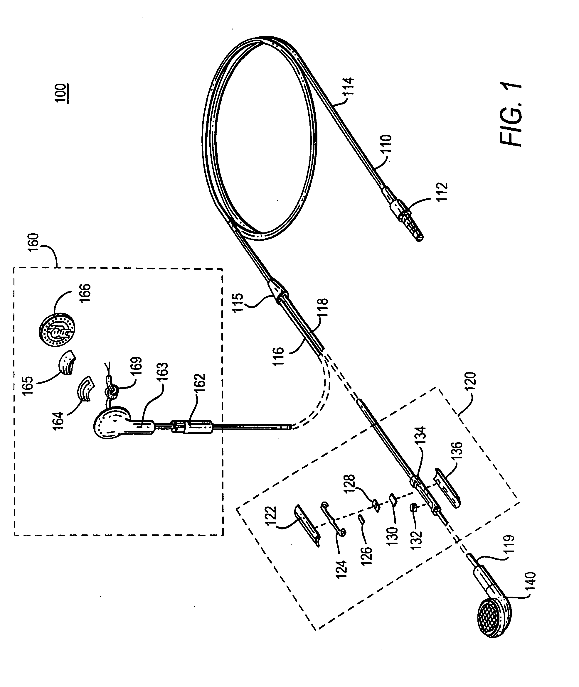
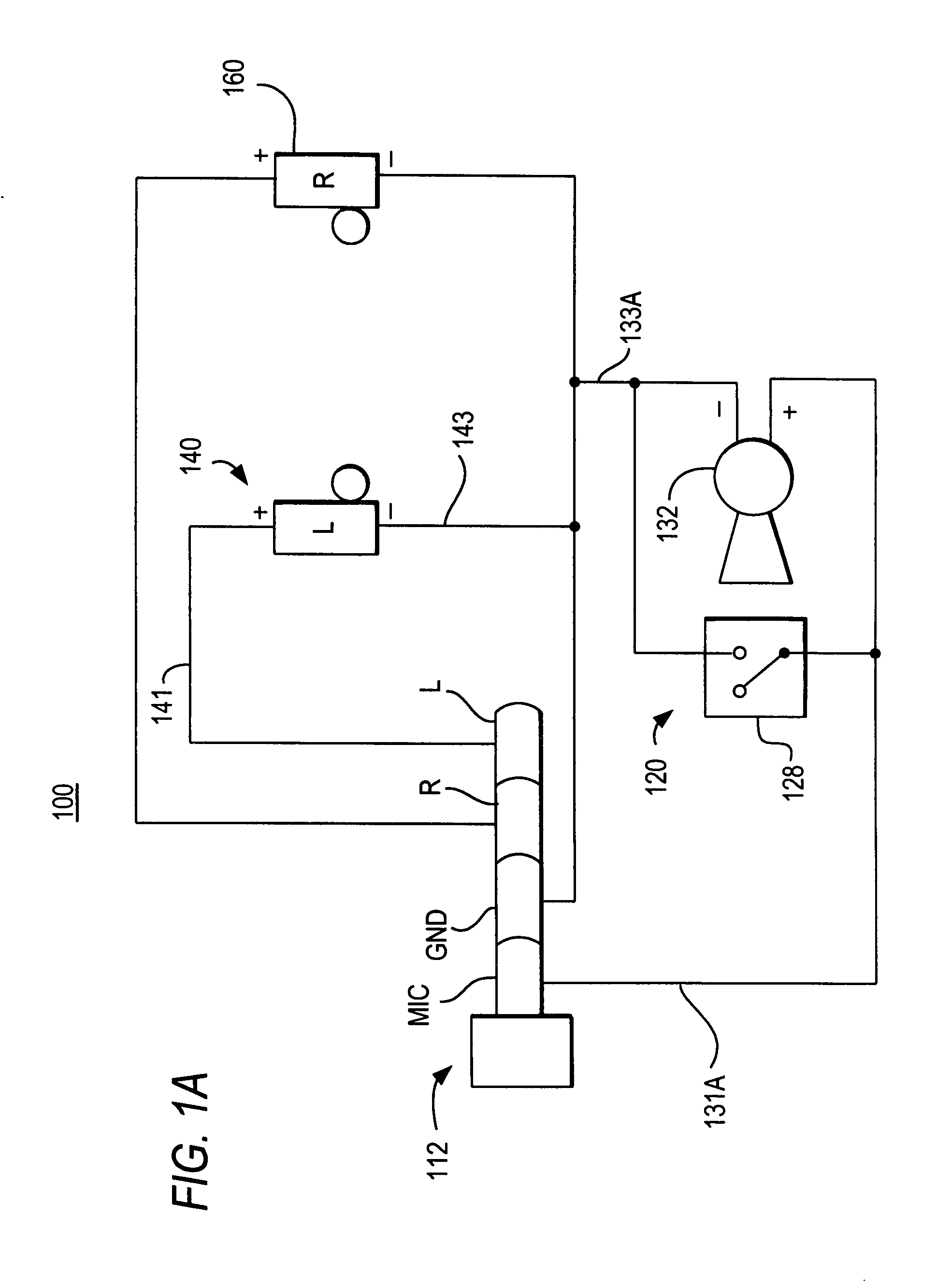
[0014]FIG. 1 shows a partial exploded view of a wired peripheral assembly system 100. System 100 can be a wired stereo headset with an integrated switch assembly and two peripheral acoustic assemblies in accordance with an embodiment of the invention. Headset system 100 can include cord assembly 110, integrated switch assembly 120, and left and right acoustic assemblies 140 and 160. FIG. 10 shows a partial exploded view of a wired monaural headset 1000 with an integrated switch assembly in accordance with an embodiment of the invention. Headset 1000 can include substantially all of the same components as stereo headset 100, with the exception that there is only one acoustic assembly instead of two. Thus, because there is a duplication of like components be...


PUM


Abstract

Headsets are provided with integrated switch assemblies. An integrated switch assembly can include a switch hidden from view by a housing. The switch can be activated when a user applies pressure to the housing. The housing may include a flexible housing cover that, when depressed, may engage the switch contained within the housing. When engaged, the switch may move or snap to a switch activation position within the housing.

Description

CROSS-REFERENCE TO RELATED APPLICATIONS[0001]This claims the benefit of U.S. Provisional Application No. 60 / 879,155, filed Jan. 6, 2007, and U.S. Provisional Application No. ______, filed Jun. 22, 2007, entitled “SINGLE USER INPUT MECHANISM FOR CONTROLLING ELECTRONIC DEVICE OPERATIONS” (Attorney Docket No. 104677-0102-001 (P5389USP1)), each of which is hereby incorporated by reference herein in its entirety.BACKGROUND OF THE INVENTION[0002]The present invention can relate to headsets and, more particularly, to wired headsets including an integrated switch.[0003]Electrical switches for controlling functions of electronic devices are well known. For example, some known media and communication devices include switches that are used to activate particular functions of the device (e.g., on / off, play, pause, select, or volume). To provide control of functions at a location remote from the media or communication device, switches that are electrically connected to and incorporated in wires ...

Claims


Application Information

Patent Timeline
Patent Type & Authority Applications(United States)
IPC IPC(8): H04R25/00
CPCH01H9/0228H01H2003/007H04R5/033H04R1/1041H04R1/1016
Inventor HANKEY, M. EVANSDANIELS, ERIC B.
Owner APPLE INC
Learn More