Optical pickup device
a pickup device and optical technology, applied in the field of optical pickup devices, can solve the problems of high price and marked problems, and achieve the effect of improving s/n ratio and low cos
- Summary
- Abstract
- Description
- Claims
- Application Information
AI Technical Summary
Benefits of technology
Problems solved by technology
Method used
Image
Examples
first embodiment
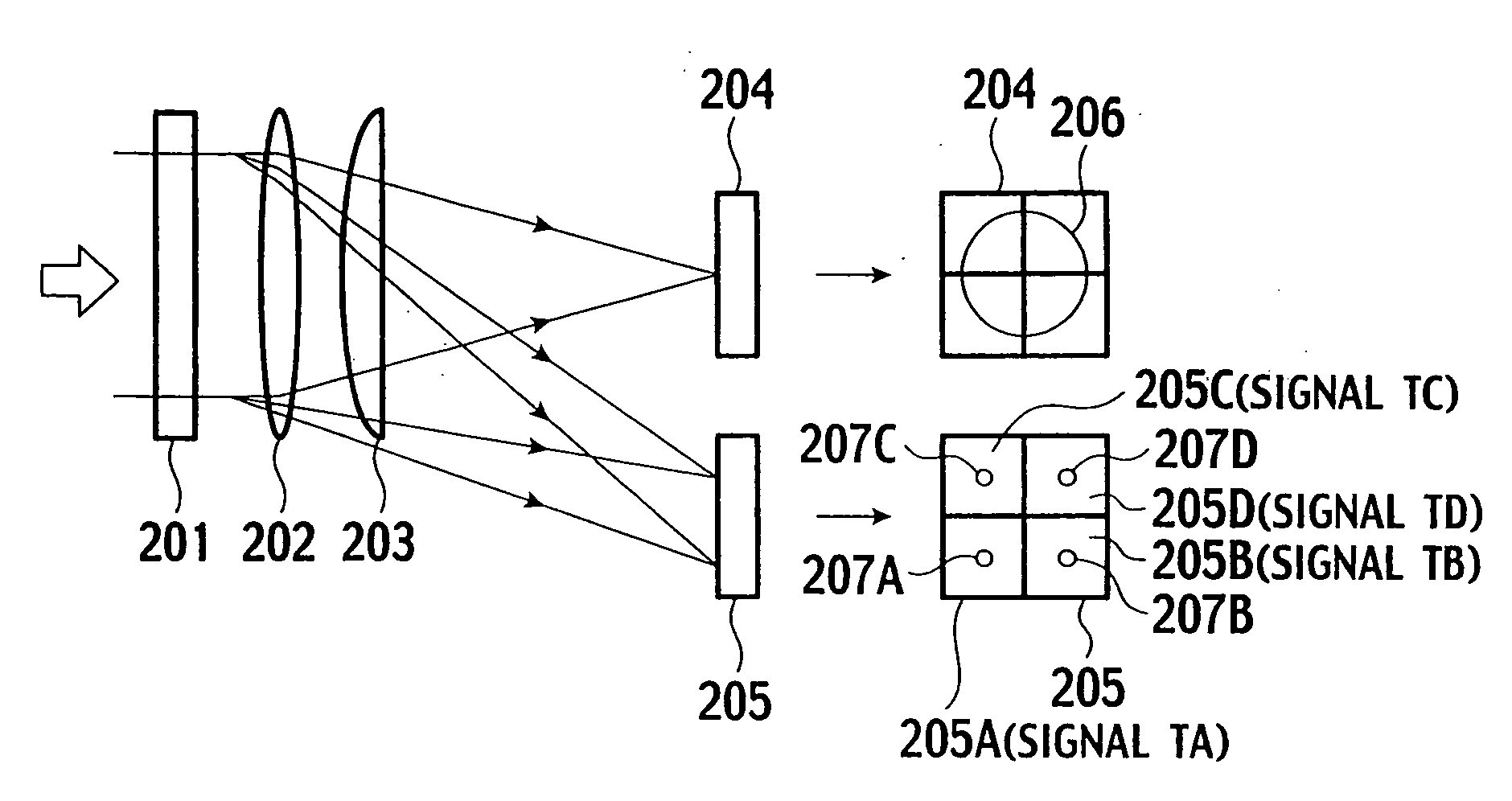
[0056]FIG. 7 is a view showing details of a detection system of the optical pickup device by way of example. As shown in FIG. 7, the reflection light LT of s-polarized light incident on the polarizing beam splitter 3 is reflected on the polarization-dependent dielectric multilayer film 3A. Then, the so-reflected light LT is divided through respective areas of an element face 8Z of a spatial divide element 8 and simultaneously supplied with astigmatism. Means for applying astigmatism may be provided by either respective areas of the element face 8A or cylindrical lenses etc. Suppose, in the first embodiment, the astigmatism is applied to the light at the respective areas of the element face 8A. The light supplied with astigmatism is received by photo acceptance cells on an acceptance surface of the photodetector 9, in the form of respective spots of the signal detection light. Subsequently, the spots are photo-electrically transferred to respective electrical signals. For each electr...
second embodiment
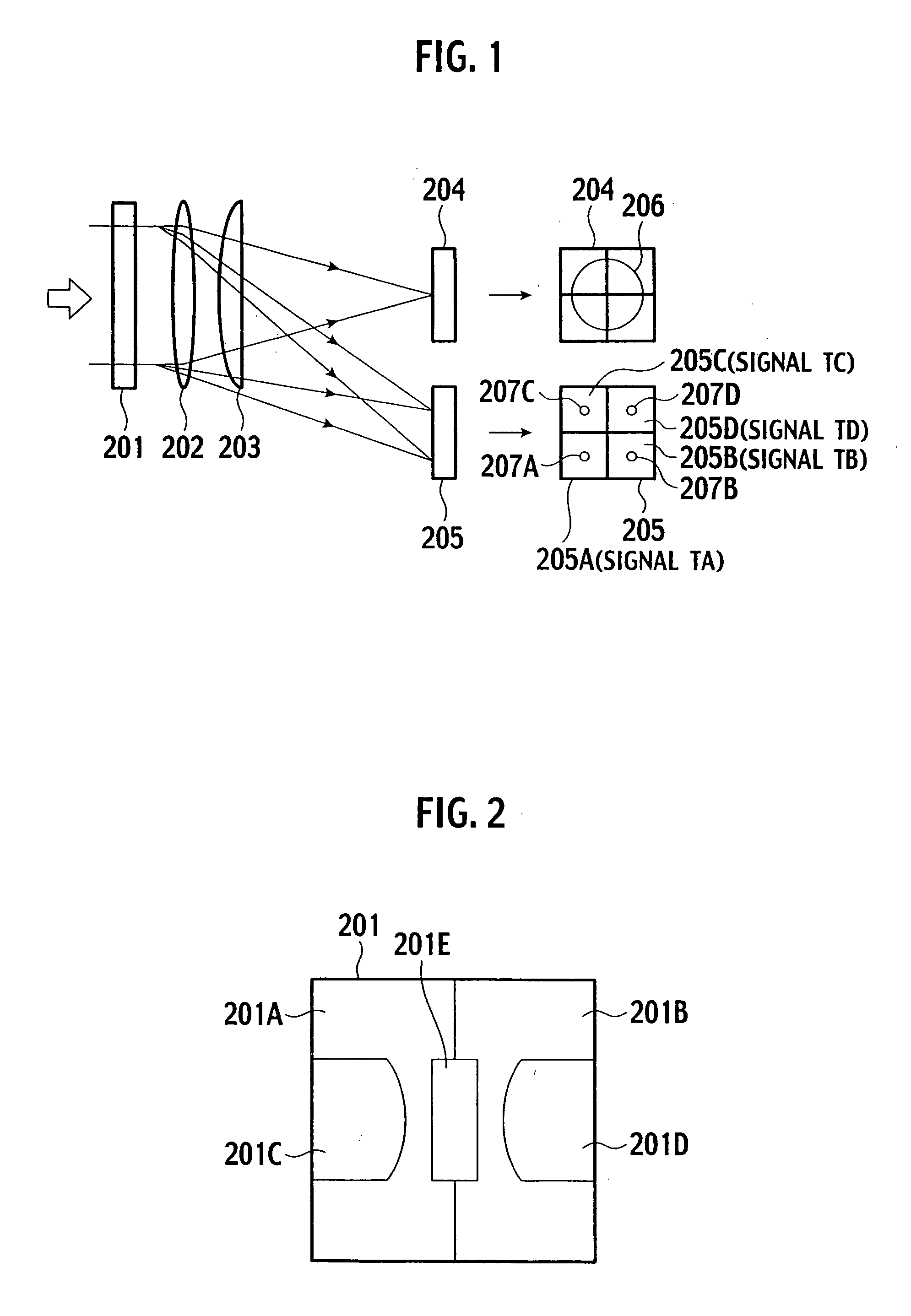
[0082]FIG. 13 shows one example of the areas of a HOE face of the diffractive optical element. FIG. 14 shows another arrangement of the photo acceptance cells of the photodetector by way of example. As shown in FIG. 13, two parting lines 50i, 50j running on a center 50P of the optical axis divide the element into four areas 50A to 50D. In the four areas 50A to 50D, light as the signal detection light is diffracted to predetermined directions by a diffraction light having the order number ma, respectively. We explain the second embodiment on the assumption of setting 1 in the order number ma (ma=1) for diffraction of the signal detection light in the areas 50A to 50D, although the order number ma may be selected from any optional number but 0.
[0083]In FIG. 13, the two parting lines 50i, 50j are arranged at angles of ±45 degrees to a radial direction where the recording tracks of the optical disc 10 are projected on a HOE face 50Z. Thus, the areas 50A to 50D are structured so as to ha...
embodiment
3rd. Embodiment
[0105]Referring to FIGS. 19 to 22, the third embodiment of the present invention, more particularly, its futures different from the first and the second embodiments will be described in detail. According to the third embodiment, the diffractive optical element 50 and the photodetector 51 of the second embodiment are replaced with a diffractive optical element 70 and a photodetector 71, respectively (FIGS. 6 and 7). The other constituents are identical to those of FIGS. 6 and 7 as well as the arrangement of optical components.
PUM
 Abstract
Description
Claims
Application Information
 - R&D
- Intellectual Property
- Life Sciences
- Materials
- Tech Scout
- Unparalleled Data Quality
- Higher Quality Content
- 60% Fewer Hallucinations
Browse by: Latest US Patents, China's latest patents, Technical Efficacy Thesaurus, Application Domain, Technology Topic, Popular Technical Reports.
© 2025 PatSnap. All rights reserved.Legal|Privacy policy|Modern Slavery Act Transparency Statement|Sitemap|About US| Contact US: help@patsnap.com


