
Method and apparatus for forming image

a technology of forming apparatus and image, which is applied in the direction of recording apparatus, printing mechanisms, instruments, etc., can solve the problems of paper creases, paper jamming, dust accumulation when sheets are left untouched,

Inactive Publication Date: 2008-07-10
KK TOSHIBA +1
View PDF11 Cites 33 Cited by
  • Summary
  • Abstract
  • Description
  • Claims
  • Application Information

AI Technical Summary

Benefits of technology

The invention is an image forming apparatus that uses ink jet technology to print images onto sheets. It includes a carriage, a mechanism for moving the carriage, a mechanism for conveying sheets, a guide member for directing sheets, a sheet stacking unit, and multiple conveying paths for sheets. The apparatus also has switching mechanisms to switch the direction of sheet feeding between different conveying paths. The technical effects of this invention include improved image quality, faster printing speed, and more efficient sheet handling.

Problems solved by technology

However, when the sheet cassette is arranged below the head recording unit, since the curvature radius of the conveying path is small, there is a problem in that, when hard paper having sturdiness of a certain degree or more such as a thick paper is fed, for example, creases are left in paper and paper jamming occurs.
On the other hand, when the means for feeding a sheet from a rear surface is used, there is a problem in that, for example, dust accumulates when sheets are left untouched.

Method used


Image

  • Method and apparatus for forming image
  • Method and apparatus for forming image
  • Method and apparatus for forming image

Examples


Embodiment Construction

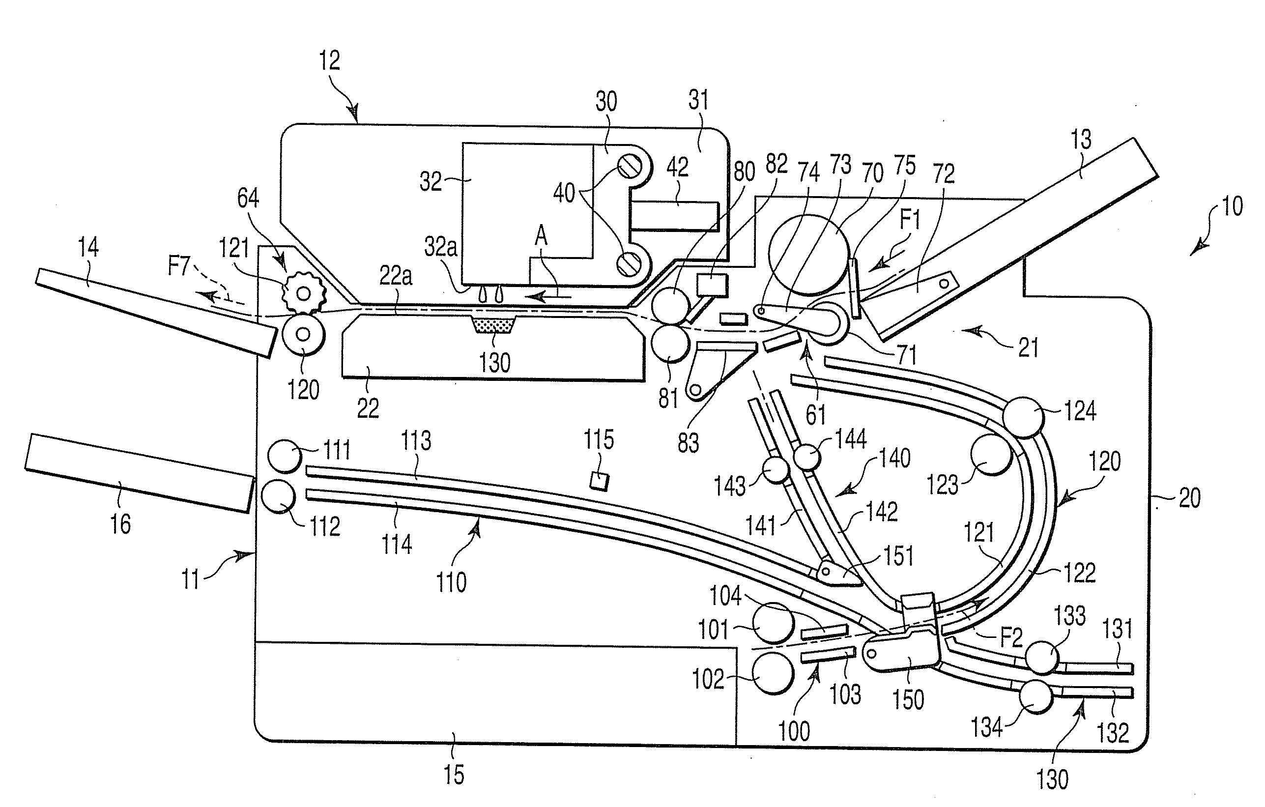
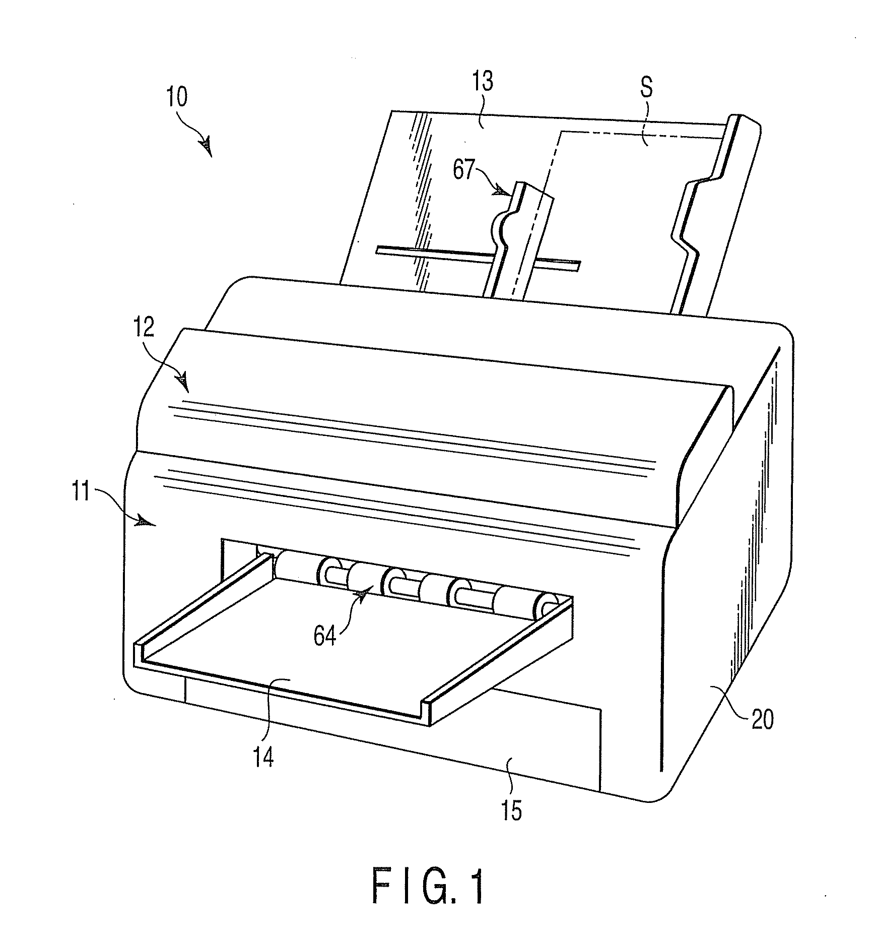
[0019]An image forming apparatus according to an embodiment of the invention will be explained with reference to FIGS. 1 to 5. FIG. 1 shows an appearance of an image forming apparatus 10. This image forming apparatus 10 has a function of printing an image on a sheet such as a print sheet. As shown in FIG. 1, the image forming apparatus 10 has a main body unit 11, a head housing unit 12 arranged on the main body unit 11, a first feed tray 13 arranged in a rear part of the main body unit 11, a discharge tray 14 arranged in a front part of the main body unit 11, a second feed tray 15 housed in a lower part of the main body unit 11, a third feed tray (a sheet stacking unit) 16, and the like.

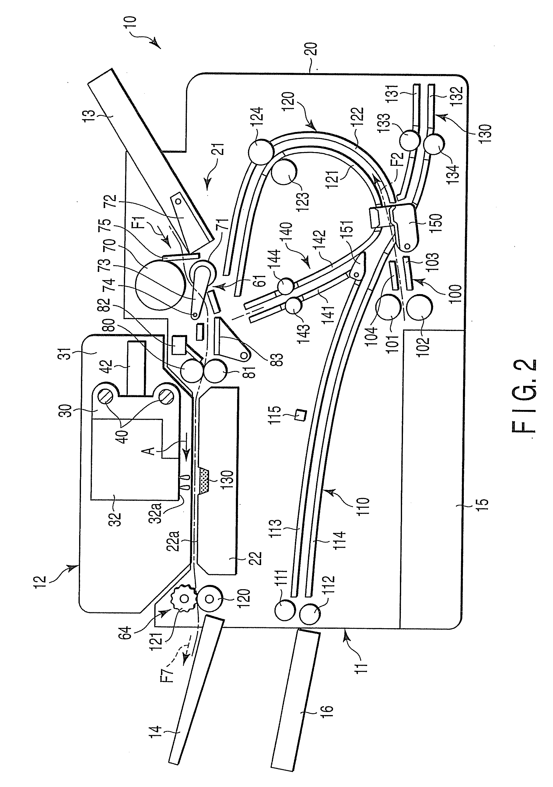
[0020]FIG. 2 schematically shows the inside of the image forming apparatus 10. The main body unit 11 includes a housing 20, a sheet conveying mechanism 21 constructed in the inside of the housing 20, a sheet guide member 22 that has a guide section 22a in the horizontal direction, and a head cleaning...


PUM


Abstract

An image forming apparatus includes a carriage mounted with a recording head, a carriage driving mechanism including a motor for reciprocatingly moving the carriage, a sheet conveying mechanism that conveys the sheet in a direction orthogonal to a moving direction of the carriage, a sheet guide member that has a guide section arranged below the recording head and opposed to the recording head and in which the sheet passes over the guide section, a sheet stacking unit that stacks and stores the sheet before printing, a first conveying path that conveys the sheet from this sheet stacking unit while causing the sheet to pass below the recording head, a second conveying path that conveys the sheet from this first conveying path to a space between the recording head and the sheet guide member while reversing the sheet, a third conveying path that conveys the sheet from the first conveying path to a temporary storing unit in a state in which a front-to-rear direction of the sheet is maintained, a fourth conveying path that conveys the sheet from the temporary storing unit to the space between the recording head and the sheet guide member in a state in which the front-to-rear direction of the sheet is maintained, a first switching mechanism that switches a conveying direction of the sheet fed from the first conveying path between the second conveying path and the third conveying path, and a second switching mechanism that guides the sheet fed from the second conveying path or the third conveying path to the fourth conveying path side.

Description

BACKGROUND OF THE INVENTION[0001]1. Field of the Invention[0002]The present invention relates to an image forming apparatus for printing an image on a sheet such as a print sheet, and, more particularly to an image forming apparatus that has a conveying path suitable for a thick paper while increasing a volume of sheets.[0003]2. Description of the Related Art[0004]There is known an image forming apparatus that has a recording head of an ink jet system and in which a head recording unit moves perpendicularly to a conveying direction of a sheet and performs image formation. In such an image forming apparatus, a sheet cassette is arranged below the head recording unit to increase a volume of sheets and sheets are fed from this sheet cassette. In this case, it is necessary to reduce a conveying path length by reason of, for example, securing printing speed. Therefore, a sheet fed from the sheet cassette passes through a conveying path having a small curvature radius. A U-turn conveying ...

Claims


Application Information

Patent Timeline
Patent Type & Authority Applications(United States)
IPC IPC(8): B41J2/01
CPCB41J13/009B41J13/0045
Inventor HIROKI, MASASHIKAIHO, SATOSHI
Owner KK TOSHIBA
Learn More