
Odu alignment procedure using circularly polarized squint

Active Publication Date: 2008-07-10
DIRECTV LLC
View PDF5 Cites 2 Cited by
  • Summary
  • Abstract
  • Description
  • Claims
  • Application Information

AI Technical Summary

Benefits of technology

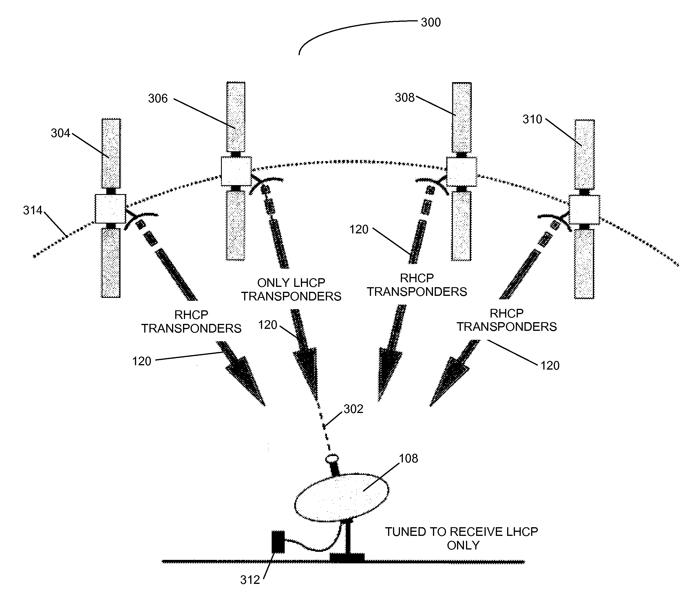
[0022]A method in accordance with the present invention comprises coarsely pointing the reflector to an orbital slot used in the satellite configuration, wherein at least one satellite in the orbital slot transmits first circularly polarized signals, and adjusting the reflector to maximize reception of the first circularly polarized signals from the orbital slot wherein a squint of the reflector is used during the adjustment.
[0024]A system in accordance with the present invention comprises a reflector, a power meter coupled to the reflector, wherein the power meter and reflector are tuned to receive first circularly polarized signals, and an alignment mechanism, coupled to the reflector, wherein the alignment mechanism is manipulated to point the reflector at an orbital slot wherein at least one satellite in the orbital slot transmits the first circularly polarized signals, and to adjust the reflector to maximize reception of the first circularly polarized signals from the orbital slot wherein a squint of the reflector is used during the adjustment.

Problems solved by technology

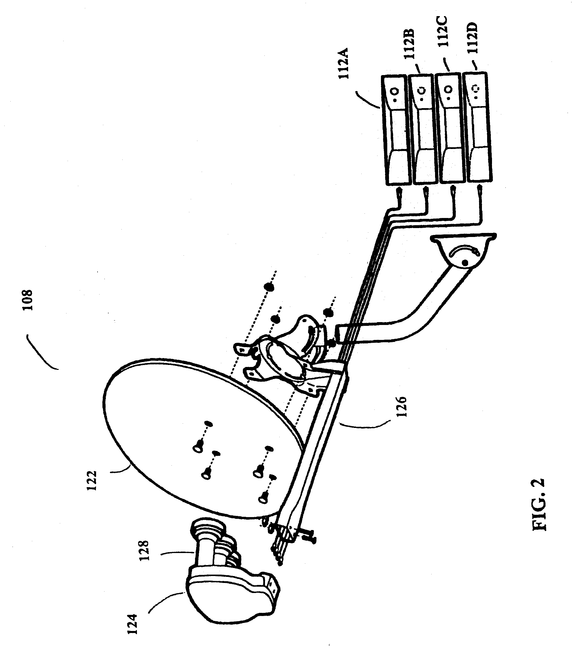
However, current IRD 112 and system 100 designs cannot tune across this entire resulting frequency band without the use of more than 4 cables, which limits the usefulness of this frequency combining feature.
However, as mentioned above, current IRDs 112 cannot use the information in some of the proposed frequencies used for downlink signals 120, thus rendering useless the information transmitted in those downlink signals 120.
However, additional satellites are being deployed that require more exacting alignment methods, and, without exacting alignment of the antenna reflector 122, the signals from the additional satellites will not be properly received, rendering these signals useless for data and video transmission.

Method used


Image

  • Odu alignment procedure using circularly polarized squint
  • Odu alignment procedure using circularly polarized squint
  • Odu alignment procedure using circularly polarized squint

Examples


Embodiment Construction

[0034]In the following description, reference is made to the accompanying drawings which form a part hereof, and which show, by way of illustration, several embodiments of the present invention. It is understood that other embodiments may be utilized and structural changes may be made without departing from the scope of the present invention.

Overview

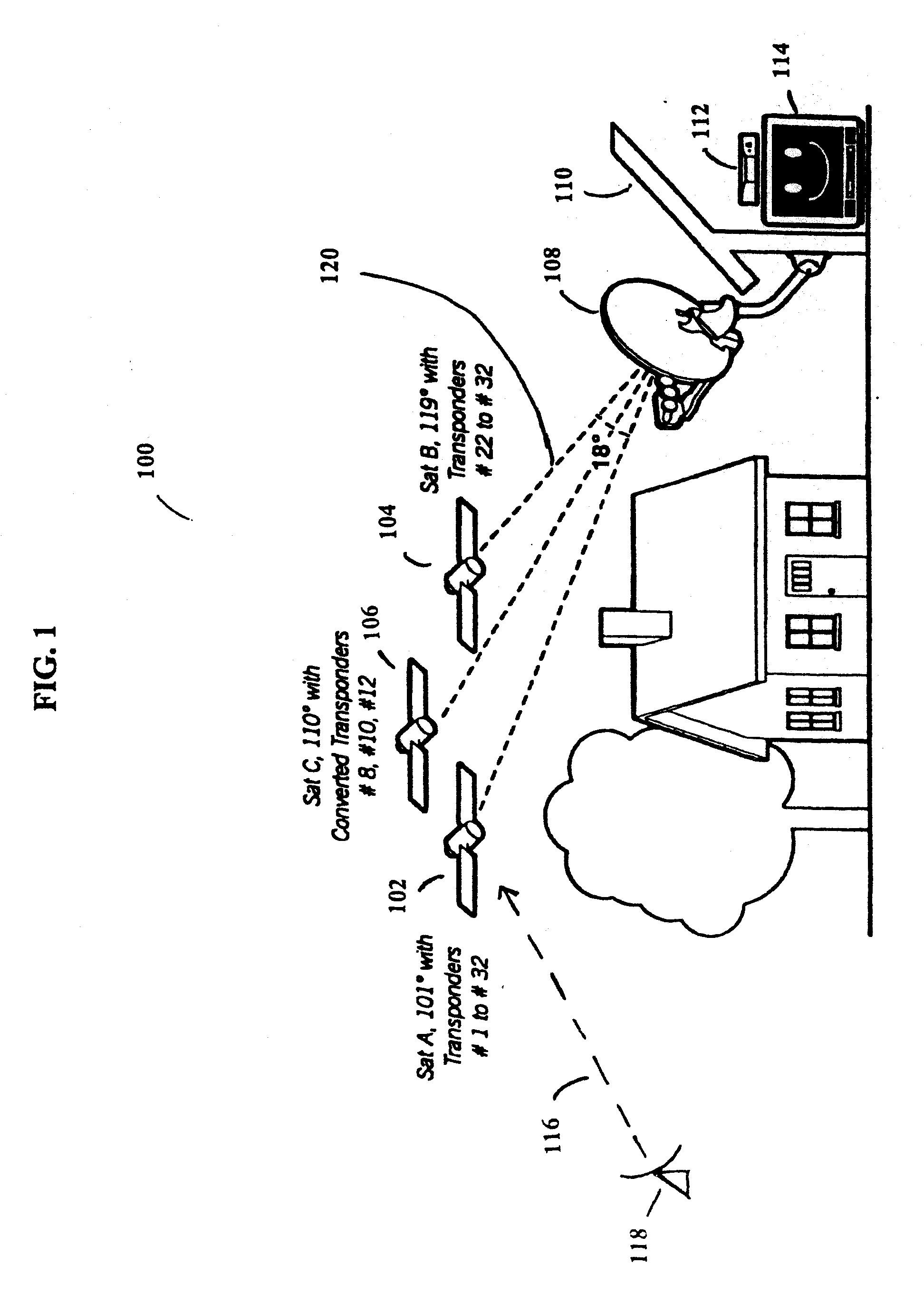
[0035]System 100 uses signals sent from Satellite A (SatA) 102, Satellite B (SatB) 104, and Satellite C (SatC) 106 that are directly broadcast to an Outdoor Unit (ODU) 108 that is typically attached to the outside of a house 110. Additionally, system 100 uses signals sent from satellites 103, which can be broadcast at a different frequency band than the signals sent by satellites 102-106 for use in system 100.

[0036]Satellites 102, 104, and 106 broadcasts downlink signals 120 in typically thirty-two (32) different frequencies, which are licensed to various users for broadcasting of programming, which can be audio, video, or data signals, ...


PUM


Abstract

A method and system for aligning an antenna reflector with satellites in a satellite configuration. A method in accordance with the present invention comprises coarsely pointing the reflector to an orbital slot used in the satellite configuration, wherein at least one satellite in the orbital slot transmits first circularly polarized signals, and adjusting the reflector to maximize reception of the first circularly polarized signals from the orbital slot. A system in accordance with the present invention comprises a reflector, a power meter coupled to the reflector, wherein the power meter and reflector are tuned to receive first circularly polarized signals, and an alignment mechanism, coupled to the reflector, wherein the alignment mechanism is manipulated to point the reflector at an orbital slot wherein at least one satellite in the orbital slot transmits the first circularly polarized signals, and to adjust the reflector to maximize reception of the first circularly polarized signals from the orbital slot.

Description

CROSS-REFERENCE TO RELATED APPLICATIONS[0001]This application claims the benefit under 35 U.S.C. §119(e) of U.S. Provisional Application Ser. No. 60 / 879,394, filed on Jan. 9, 2007, by Gustave R. Stroes and Benjamin Mui, entitled “ODU ALIGNMENT PROCEDURE USING CIRCULARLY POLARIZED SQUINT,” which application is incorporated by reference herein.[0002]This application is related to the following application:[0003]Application Ser. No. 60 / 879,376, filed Jan. 9, 2007, by Gustave R. Stroes et al, entitled “ODU ALIGNMENT PROCEDURE USING CIRCULARLY POLARIZED SIGNALS ALLOCATED TO SPECIFIC SATELLITES,” which application is incorporated by reference herein.BACKGROUND OF THE INVENTION[0004]1. Field of the Invention[0005]The present invention relates generally to a satellite receiver system, and in particular, to an alignment method for multi-band consumer receiver antennas.[0006]2. Description of the Related Art[0007]Satellite broadcasting of communications signals has become commonplace. Satelli...

Claims


Application Information

Patent Timeline
IPC IPC(8): H01Q3/00
CPCH01Q1/1257H01Q25/007H01Q19/12H01Q3/06
Inventor STROES, GUSTAVE R.MUI, BENJAMIN
Owner DIRECTV LLC
Learn More