
Safe Electric Braking Device for Printing Presses and Method of Electrically Braking an Electric Drive in a Machine Processing Printing Material

a technology of electric brake and printing press, which is applied in the direction of motor/generator/converter stopper, dynamo-electric converter control, ac motor stopper, etc., can solve the problems of complex and large mechanical brakes that cannot be dispensed, and the electric braking device cannot reliably brake the printing press down to a standstill

Inactive Publication Date: 2008-06-26
HEIDELBERGER DRUCKMASCHINEN AG
View PDF10 Cites 18 Cited by
  • Summary
  • Abstract
  • Description
  • Claims
  • Application Information

AI Technical Summary

Benefits of technology

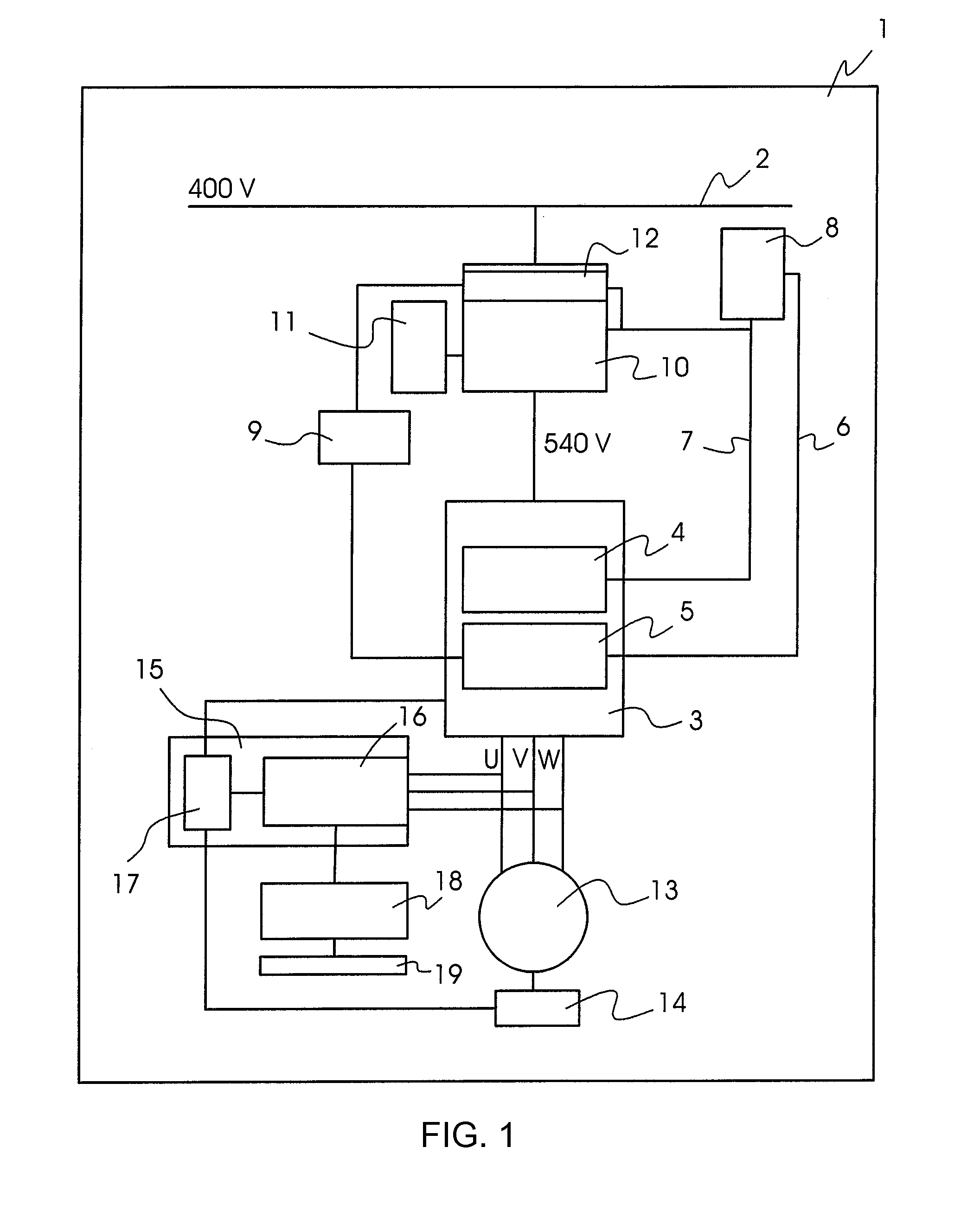
[0014]A particular advantage of the present invention is that, during the braking operation, above a predetermined maximum rotational speed, a mechanical brake of the drive motor is open. In this case, the mechanical brake is only used to lock the braked motor against rotation. The mechanical brake is not closed until the motor operates only at a predetermined maximum rotational speed. This maximum rotational speed is low enough so that a small mechanical braking device is sufficient to ensure safe locking of the drive motor. Moreover, the fact that the mechanical brake will only be activated below the predetermined maximum rotational speed protects the relatively small mechanic brake against overloading and damage.
[0015]In accordance with an additional embodiment of the invention, the power electronics is separated from the DC voltage intermediate circuit during braking through the further braking device. Generator-type braking through the further, redundant braking device is carried out when there is a failure in the power electronics. In order to preclude negative effects of the electric drive motor or the further electric braking device on the DC voltage intermediate circuit through the failed power electronics, the separation of the power electronics from the DC voltage intermediate circuit is carried out in the case of a failure.
[0016]In order to meet current safety requirements, a braking of the electric drive motor to a standstill must be possible within not more than 10 seconds. Consequently, the further electric braking device and the regular generator-type braking operation must be selected in such a way that this predetermined time period is not exceeded.
[0017]Other features which are considered as characteristic for the invention are set forth in the appended claims.
[0018]Although the invention is illustrated and described herein as embodied in a safe electric braking device for printing presses and a method of electrically braking an electric drive in a machine for processing printing material, it is nevertheless not intended to be limited to the details shown, since various modifications and structural changes may be made therein without departing from the spirit of the invention and within the scope and range of equivalents of the claims.
[0019]The construction and method of operation of the invention, however, together with additional objects and advantages thereof will be best understood from the following description of specific embodiments when read in connection with the accompanying drawings.BRIEF DESCRIPTION OF THE SEVERAL VIEWS OF THE DRAWING

Problems solved by technology

If the converter breaks down due to a failure, the electric braking device can no longer reliably brake the printing press down to a standstill.
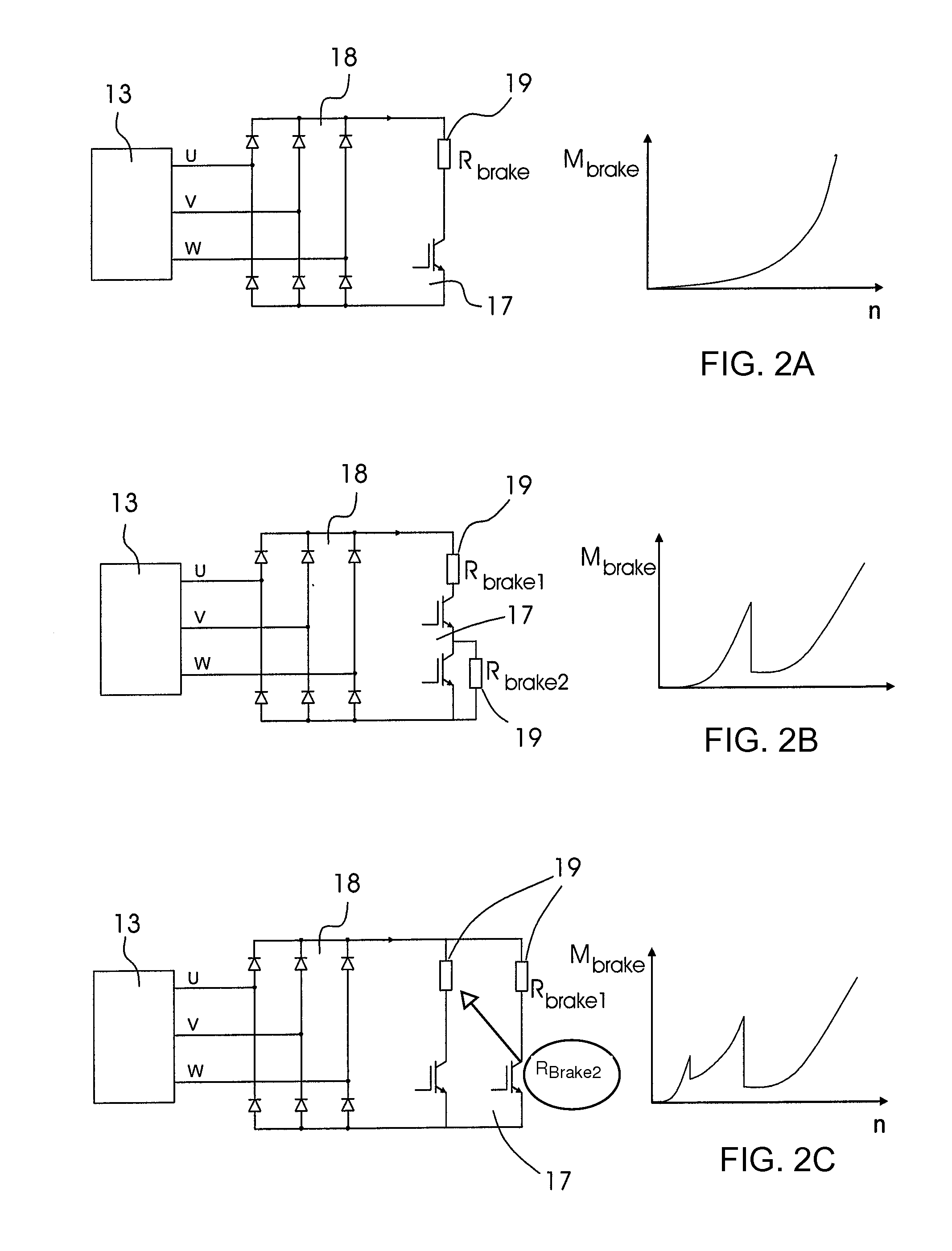
Due to the further electric braking device, a complex and large mechanical brake can be dispensed with.

Method used


Image

  • Safe Electric Braking Device for Printing Presses and Method of Electrically Braking an Electric Drive in a Machine Processing Printing Material
  • Safe Electric Braking Device for Printing Presses and Method of Electrically Braking an Electric Drive in a Machine Processing Printing Material
  • Safe Electric Braking Device for Printing Presses and Method of Electrically Braking an Electric Drive in a Machine Processing Printing Material

Examples


Embodiment Construction

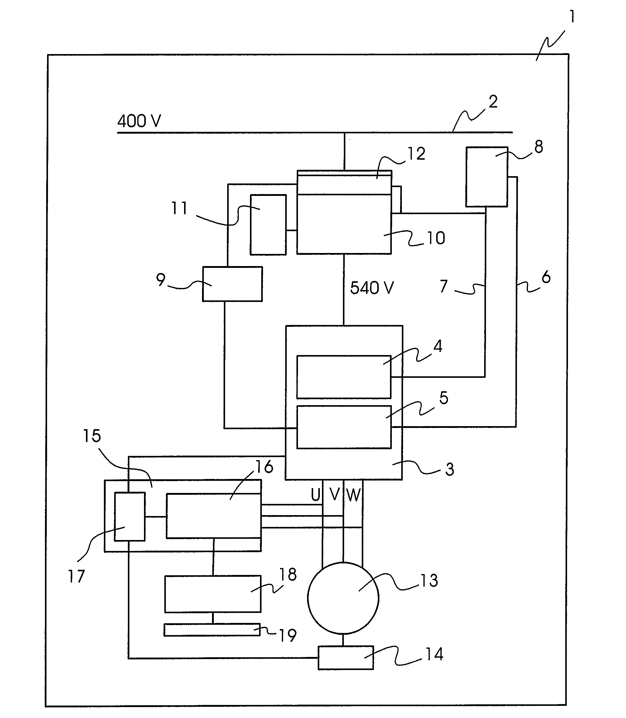
[0024]Referring now to the figures of the drawings in detail and first, particularly, to FIG. 1 thereof, there is seen a printing press 1 including at least one electric drive motor 13. This electric drive motor or drive 13 may be constructed as a main drive and may drive all of the cylinders in the printing press 1 through a gear train. In large-format printing presses, the drive motor 13 may have an electric wattage of more than 100 KW because it needs to rotate huge masses due to the large cylinders. The electric drive motor 13 has a three-phase connection U, V, W to a motor power electronics 3. This motor power electronics 3 includes a drive computer 4 and a safety computer 5, both of which may have a fundamentally identical construction. During normal operation, the drive computer 4 controls the motor power electronics 3 and a converter included in the motor power electronics 3, in order to adjust the electric drive motor 13 to a respective operating condition of the printing p...


PUM


Abstract

A method and device for electrically braking an electric drive in a machine for processing printing material, includes a power electronics connected between the electric drive and a DC voltage intermediate circuit. A further electric braking device is switchable between the electric drive and the power electronics. Upon a failure of a power system, a computer initiates a generator-type braking operation through the power electronics. The further electric braking device is switched on upon the failure of the power electronics.

Description

CROSS-REFERENCE TO RELATED APPLICATION[0001]This application claims the priority, under 35 U.S.C. § 119, of German Patent Application DE 10 2006 061 347.3, filed Dec. 22, 2006; the prior application is herewith incorporated by reference in its entirety.BACKGROUND OF THE INVENTIONField of the Invention[0002]The present invention relates to an electric braking device for machines for processing printing materials, including an electric drive to be braked that is supplied with electric power through a power converter during motor operation and feeds back electric power to the power converter during braking. The invention also relates to a method of electrically braking an electric drive in a machine for processing printing material.[0003]Printing presses include one or more electric motors for driving rotary components, such as printing cylinders and transport cylinders. Due to the high masses of the cylinders, the rotating components have a relatively high lag time when the electric d...

Claims


Application Information

Patent Timeline
Patent Type & Authority Applications(United States)
IPC IPC(8): H02P3/14
CPCB41F13/016H02P3/22H02P3/14B41F33/12
Inventor ALEXANDER, ANDREASBECHTLER, JOCHENDURR, WOLFGANGHARTMANN, KLAUSKLEIBAUMHUTER, KLAUS-DIETERMEYER, HELMUT
Owner HEIDELBERGER DRUCKMASCHINEN AG
Learn More