
Dispensing Support Device and Dispensing Support Method

a technology of support device and support device, which is applied in the direction of supporting apparatus, instruments, de-stacking articles, etc., can solve the problems of high price, high cost, and inability to take any action, so as to reliably prevent the wrong dosage of drugs, simple configuration, and low cost

Inactive Publication Date: 2008-06-26
YUYAMA MFG CO LTD
View PDF5 Cites 24 Cited by
  • Summary
  • Abstract
  • Description
  • Claims
  • Application Information

AI Technical Summary

Benefits of technology

The present invention aims to provide a dispensing support device and method that allows multiple pharmacists to perform dispensing simultaneously in a simple and low-cost configuration. The current systems are either manual and limited in their functionality or automatic and expensive. The invention provides a solution that allows for efficient and effective drug management.

Problems solved by technology

Thus, a plurality of direction notes cannot be read at a time to permit a plurality of pharmacists to perform dispensing simultaneously.
Moreover, it is impossible to take any action even when a drug has been taken out from a wrong rack.
With an automatic type, the device is upsized and complicated, and thus high-priced.
A drug management system is only capable of providing record of dispensing operation, failing to provide an environment that permits a plurality of persons to perform the operation simultaneously.

Method used


Image

  • Dispensing Support Device and Dispensing Support Method
  • Dispensing Support Device and Dispensing Support Method
  • Dispensing Support Device and Dispensing Support Method

Examples


first embodiment

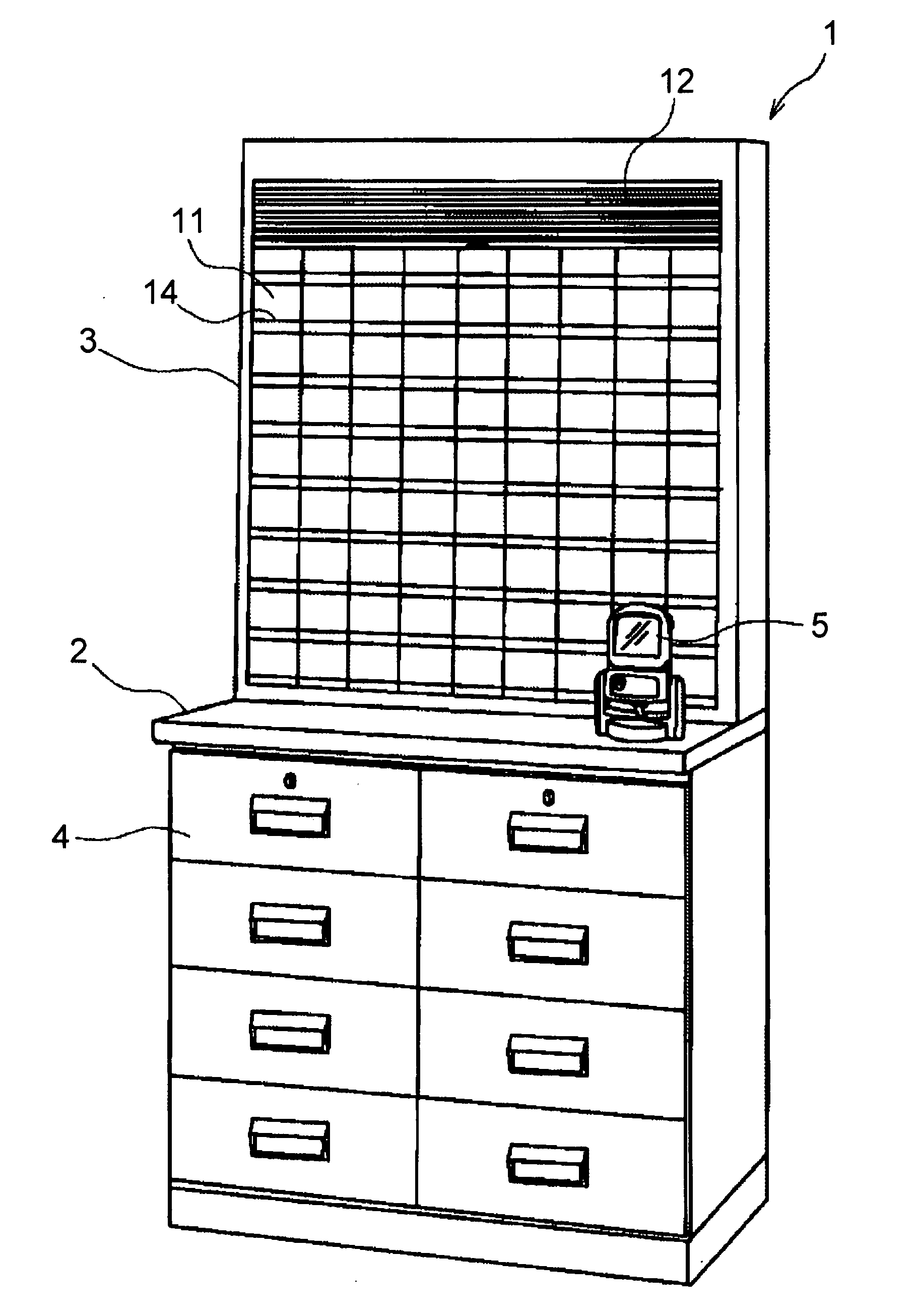
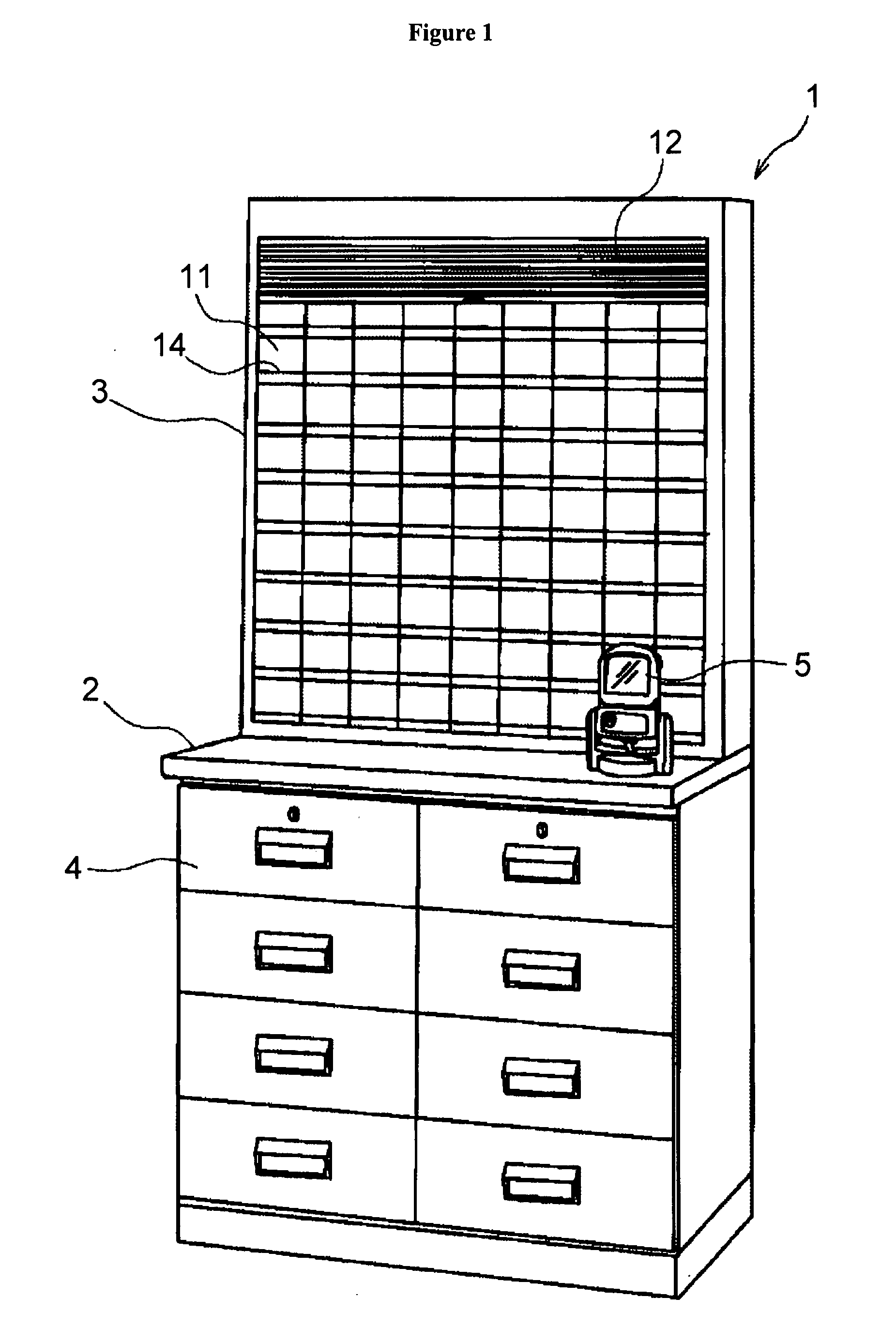
[0039]FIG. 1 shows the exterior of a dispensing support device 1 according to a first embodiment. This dispensing support device 1 is formed by placing a drug rack 3 on a dispensing base 2.

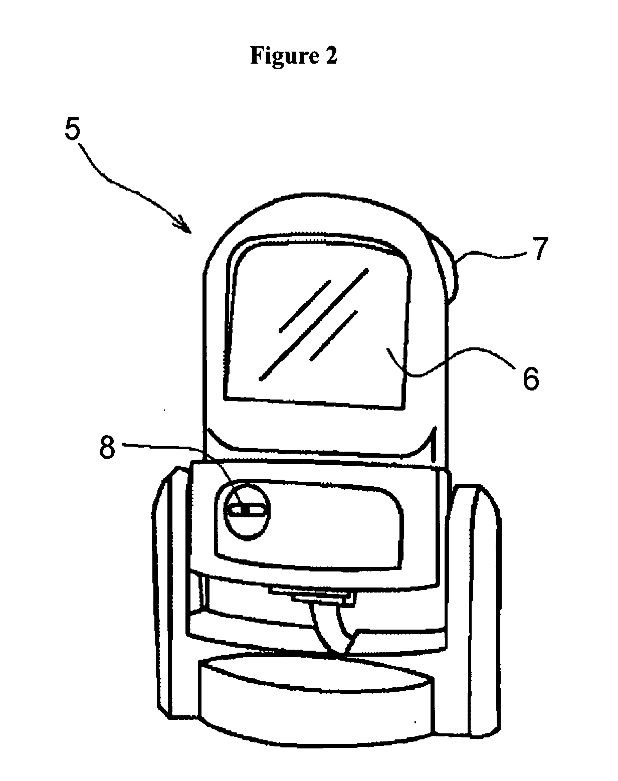
[0040]The dispensing base 2 includes a plurality of drawers 4 drawably provided in a front side thereof, and has health related members such as catheter, poultices, gauze, or the like, and drugs such as guttae or the like, which are contained inside thereof. In addition, on the dispensing base 2, a bar code reader 5 shown in FIG. 2 is set. This bar code reader 5 includes a bar code identification part 6, a RFID antenna 7 (RFID: Radio Frequency Identification), a buzzer 8, and the like. The bar code identification part 6 identifies a bar code A printed on a dispensing direction note P (see FIG. 8), whereby prescription data for a patient written on a direction note P is extracted from among those inputted from a host computer 9 (data concerning contents of prescriptions created by a doctor). The RF...

second embodiment

[0067]FIGS. 18 and 19 show a dispensing support device 30 according to a second embodiment. This dispensing support device 30 differs from the one according to the first embodiment mainly in the following point. Hereinafter, in the description and figures below, those portions configured in the same manner are provided with the same numerals and thus omitted from the description.

[0068]In each cassette 11 of the drug rack 3, an approaching object detection sensor 31 is provided as shown in FIG. 20. In addition, in each cassette 11, a first display part 32 is provided as shown in FIG. 21. Further, also in each drawers 4, a second display part 33 is provided on the center of the holding part 4b provided on the front surface and a third display part 34 is provided on the top surface of a partition wall 4a inside the drawers 4, as shown in FIGS. 22 through 24.

[0069]Moreover, below the drug rack 3, a key hole 35 is provided which permits insertion of a shutter open-close key, not shown. T...


PUM


Abstract

[Object] To permit a plurality of pharmacists to perform dispensing efficiently and simultaneously despite of simple, low-cost configuration.[Means for Settlement] There are provided: responsible a pharmacist identification means 7 which is provided at each container 14 of a drug rack 3 where a drug D is contained and which identifies a responsible pharmacist; a memory 25 where the pharmacist data is stored; and a control means 24 which, as a result of inputting the prescription data, associates the prescription data and the pharmacist data stored in a memory means 25 with each other to create a prescription table, stores the prescription table into the memory means 25, and then, when the drug is taken out from the drug rack 3, refers to the prescription table based on the pharmacist data of the pharmacist identified by the responsible pharmacist identification means 7, and judges whether or not the pharmacist is permitted to perform dispensing of the drug to be taken out from the drug rack 3.

Description

TECHNICAL FIELD OF THE INVENTION[0001]The present invention relates to a dispensing support device and a dispensing support method.BACKGROUND OF RELATED ARTS[0002]Conventionally, in performing dispensing, a pharmacist takes a look at a prescription and then takes out a drug from a drug rack. However, with this method, human error, such as misunderstanding of the prescription or the like, is likely to occur. In addition, there is a large difference in the workability depending on a difference in the skill level among pharmacists.[0003]Thus, to support dispensing, a manual device (for example, see patent document 1) or an automatic device (for example, see patent documents 2 through 4) have been proposed.[0004]In addition, a drug management system has been proposed in which an IC chip is provided to a wrist band fitted on a person responsible for dispensing so that, when information of the responsible person stored on the IC chip is read by an antenna provided in a container where a d...

Claims


Application Information

Patent Timeline
Patent Type & Authority Applications(United States)
IPC IPC(8): G07F9/02A47B81/00G07F11/00A47G29/00G06Q10/00
CPCG06Q10/10G07F17/40G07F17/0092G07F11/70A61J3/00
Inventor YUYAMA, HIROYUKISHIGEYAMA, YASUHIROKASUYA, MASAHIKOYASUDA, SHINYA
Owner YUYAMA MFG CO LTD
Learn More