Solid particle counting system with valve to allow reduction of pressure pulse at particle counter when vacuum pump is started

a technology of solid particle counting and vacuum pump, which is applied in the direction of machines/engines, electrical control, instruments, etc., can solve the problems of many health problems, complicated calibration procedures, and complicated experimental setup and operation procedures to use the cpc for measuring combustion engine or vehicle exhaust aerosols, so as to avoid work fluid backflow

Inactive Publication Date: 2008-06-26
HORIBA LTD
View PDF11 Cites 26 Cited by
  • Summary
  • Abstract
  • Description
  • Claims
  • Application Information

AI Technical Summary

Benefits of technology

[0009]It is an object of the invention to provide a reliable, repeatable, and easily operated instrument to measure solid particle emissions from engine or vehicle exhaust, and to use as an instrument for certification, and research and development.
[0010]The invention comprehends a solid particle counting system (SPCS) that in one embodiment comprises mass flow controllers, flow orifices, pressure sensors, thermocouples, ball valves, a cyclone, an evaporation tube, etc. The concept of a wide range continuous diluter is used on the hot diluter (PND1) and the cold diluter (PND2). These diluters give accurate and wide range dilution ratios while high solid particle penetrations are achieved. Due to real time dilution ratios available from the hot diluter (PND1) and the cold diluter (PND2), the instrument gives more accurate particle measurement in real time.
[0012]In accordance with one aspect of the invention, a solid particle counting system includes a diluter arrangement, a particle counter, and a flow splitter. The diluter arrangement mixes the dilution gas with flowing sample gases. The flow splitter receives the output flow from the diluter arrangement, provides a portion of this flow to the particle counter, and provides a by-pass flow that is received by a vacuum pump. A second flow route to the particle counter includes a valve arranged such that opening the valve during the starting of the vacuum pump reduces a pressure pulse at the particle counter caused by the starting of the vacuum pump, thereby avoiding work fluid backflow from the particle counter prior to the vacuum pump stabilizing.
[0013]Advantageously, by including the valve arranged on a second flow route to the particle counter, the pressure pulse that occurs when the vacuum pump is started can be reduced to avoid work fluid backflow from the particle counter prior to the vaccum pump stabilizing. After the vacuum pump has stabilized, the valve is closed. This valve arrangement is useful, for example, at the start of a system zero check or at the start of operating the system in the sample mode.

Problems solved by technology

Many studies show particles from diesel engine exhausts cause many health problems.
However, the experimental setup and operation procedure and calibration to use the CPC for measuring combustion engine or vehicle exhaust aerosols are pretty complicated.

Method used


Image

  • Solid particle counting system with valve to allow reduction of pressure pulse at particle counter when vacuum pump is started
  • Solid particle counting system with valve to allow reduction of pressure pulse at particle counter when vacuum pump is started
  • Solid particle counting system with valve to allow reduction of pressure pulse at particle counter when vacuum pump is started

Examples


Embodiment Construction

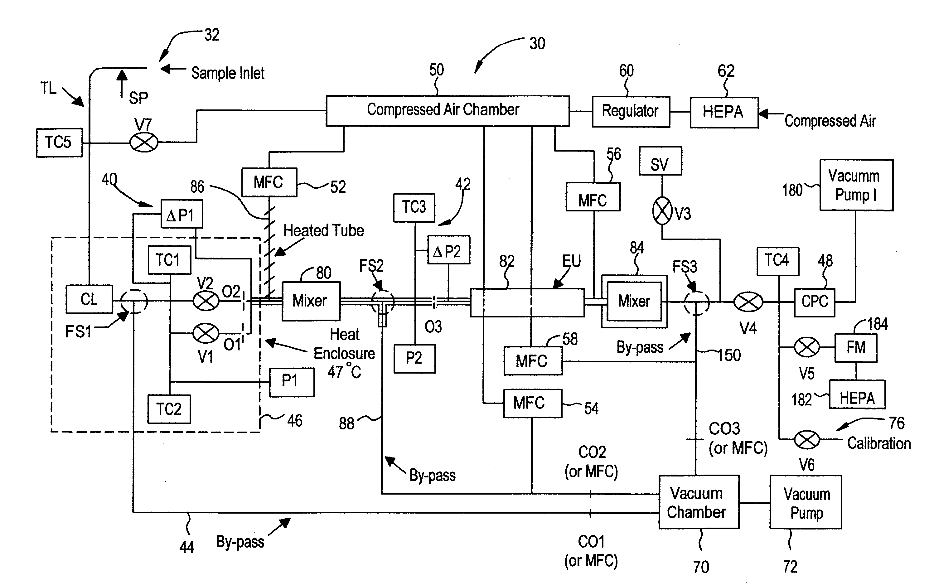
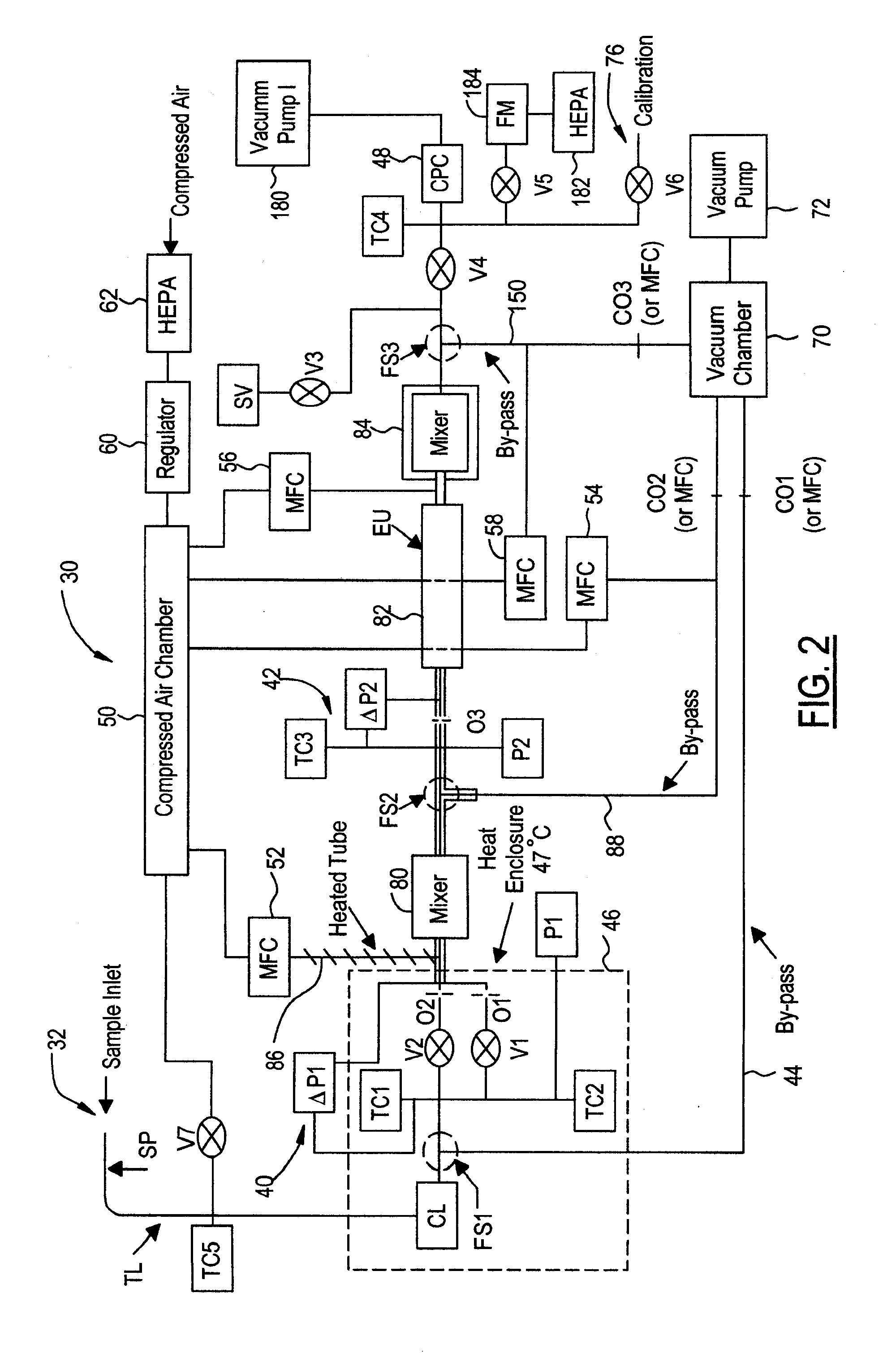
[0021]FIGS. 2-6 illustrate the preferred embodiment of a solid particle counting system (SPCS) made in accordance with the invention. It is to be appreciated that those skilled in the art may implement various aspects of the system in other ways and that the following description is intended to be exemplary and not intended to be limiting. Specifically, the following description relates to the preferred embodiment illustrated in FIGS. 2-6, and other embodiments of the invention may be implemented in other ways.

[0022]In the following description of the preferred embodiment, the work principle of the instrument is explained in three aspects, general description, detail components, and functions. To understand how the SPCS works, the three sections should be considered together.

General Description

[0023]With reference to FIG. 2, the solid particle counting system (SPCS) in the preferred embodiment is generally indicated at 30. The SPCS sample inlet is indicated at 32. SPCS 30 includes v...


PUM


Abstract

A solid particle counting system for measuring solid particle number concentrations from engine or vehicle exhausts in real-time includes a diluter arrangement, a particle counter, and a flow splitter. The diluter arrangement mixes the dilution gas with flowing sample gases. The flow splitter receives the output flow from the diluter arrangement, provides a portion of this flow to the particle counter, and provides a by-pass flow that is received by a vacuum pump. A second flow route to the particle counter includes a valve arranged such that opening the valve during the starting of the vacuum pump reduces a pressure pulse at the particle counter caused by the starting of the vacuum pump, thereby avoiding work fluid backflow from the particle counter prior to the vacuum pump stabilizing.

Description

BACKGROUND OF THE INVENTION[0001]1. Field of the Invention[0002]The invention relates to measuring solid particle number concentrations from engine or vehicle exhausts in real-time.[0003]2. Background Art[0004]Engine exhaust particles mainly consist of solid and volatile particles. Many studies show particles from diesel engine exhausts cause many health problems. To understand how particles impact human health, characteristics of particles from engines and vehicles should be investigated. Thus, the accurate measurement of particles emitted by modern diesel and gasoline vehicles is needed.[0005]European PMP (Particle measurement programme) has recommended an approach to measure solid particle number emission from light-duty diesel vehicles. The system is shown in FIG. 1, and consists of a pre-classifier 10, a hot diluter (PND1) 12, an evaporation tube 14, a cold diluter (PND2) 16, and a condensation particle counter (CPC) 18. The pre-classifier 10 is used to keep the cutoff size of ...

Claims


Application Information

Patent Timeline
IPC IPC(8): G01N15/06G01M15/10
CPCF01N11/00F02D41/1466G01N2001/2264G01N1/2252G01N15/065G01N1/2211
Inventor WEI, QIANGPORTER, SCOTT T.ASANO, ICHIRORAHMAN, MONTAJIR MD.KUSAKA, TAKESHI
Owner HORIBA LTD
Why Eureka
Try Eureka