
Wind turbine tower suspension means

a technology of suspension unit and wind turbine, which is applied in the direction of wind energy generation, mechanical equipment, machines/engines, etc., can solve the problems of weakening the tower structure, significant structural limitations for which no compensation is provided, and the bolting of especially the interior tower components such as ladders, cables, etc., to facilitate the de-attachment of the suspension unit and reduce the de-attachment force

Inactive Publication Date: 2008-06-19
VESTAS WIND SYST AS
View PDF29 Cites 12 Cited by
  • Summary
  • Abstract
  • Description
  • Claims
  • Application Information

AI Technical Summary

Benefits of technology

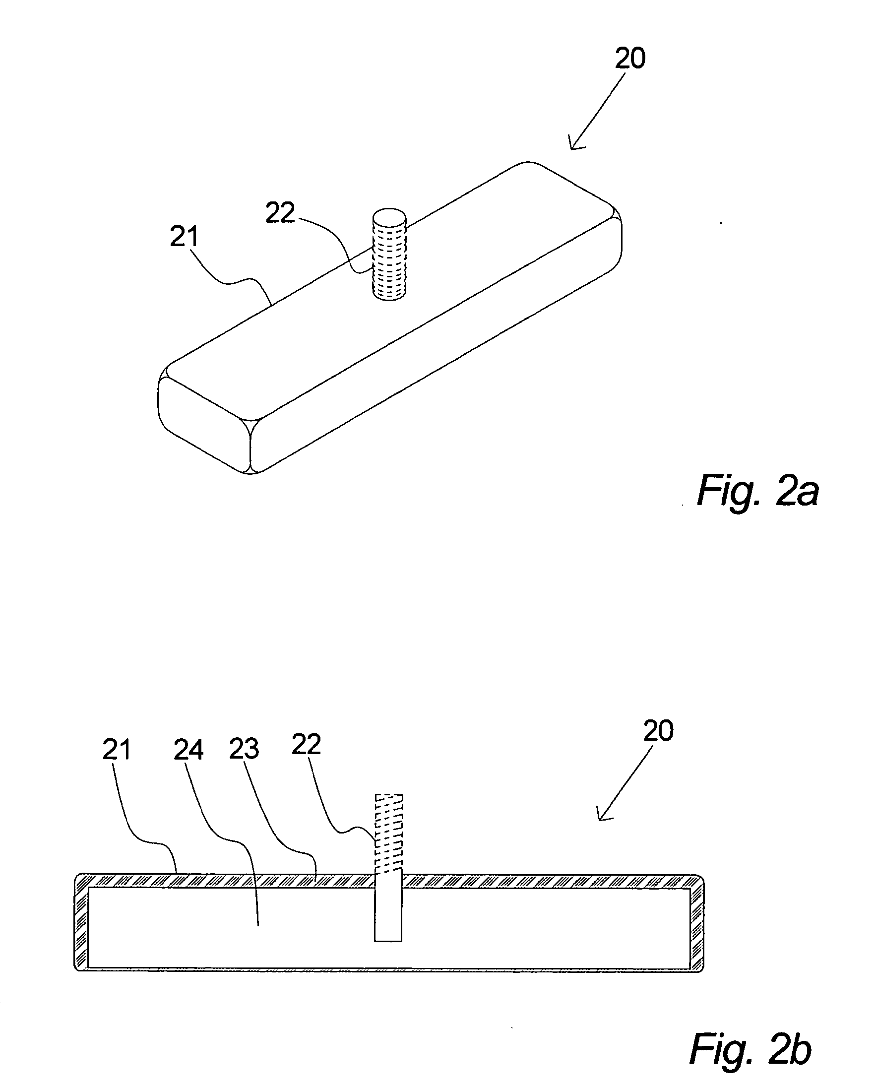
[0010]According to the invention, the wind turbine suspension units may be attached to the wind turbine tower, preferably completely or partly to the inner wall by means of magnetic attraction forces, thereby preventing structure-weakening attachments to the tower or part of the tower.
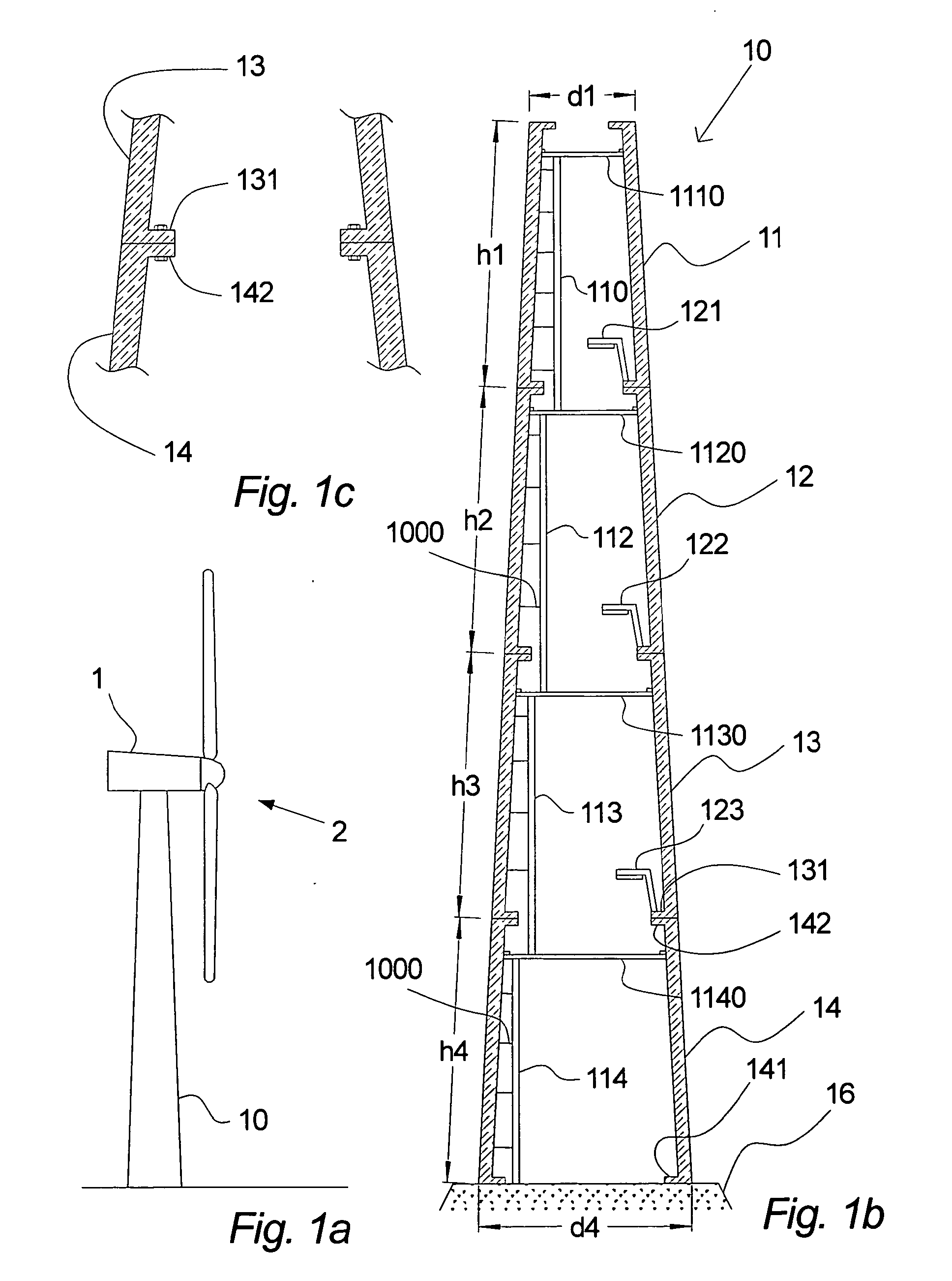
[0062]When at least one of said mechanical attachment areas (131, 142) facilitates mechanical attachment of at least one suspension unit (20; 60) and suspension to said at least one of said mechanical attachment areas (131, 142), a further advantageous embodiment of the invention has been obtained.

Problems solved by technology

One of several problems associated with the above-described wind turbine towers is that the welding or bolting of especially the interior tower components such as ladders, cables, etc., weaken the tower structure.
In some cases, it is possible to compensate for this problem by taking relatively costly precautions, which may, in turn, infer significant structural limitations for which no compensation is made.

Method used


Image

  • Wind turbine tower suspension means
  • Wind turbine tower suspension means
  • Wind turbine tower suspension means

Examples


Embodiment Construction

[0074]Most large wind turbines are delivered with tubular steel towers manufactured in sections of 20-30 meters with flanges at both ends, and bolted together on the site. The towers are conical (i.e. the diameter increases towards the base) in order to increase strength and save materials at the same time.

[0075]The production costs of the wind turbine towers are relatively high compared with the manufacturing costs of the complete wind turbine construction. Moreover, these costs increase proportionately with the height and especially if it exceeds around fifty meters.

[0076]It is therefore quite important with respect to the final cost of energy to build towers as optimally as possible.

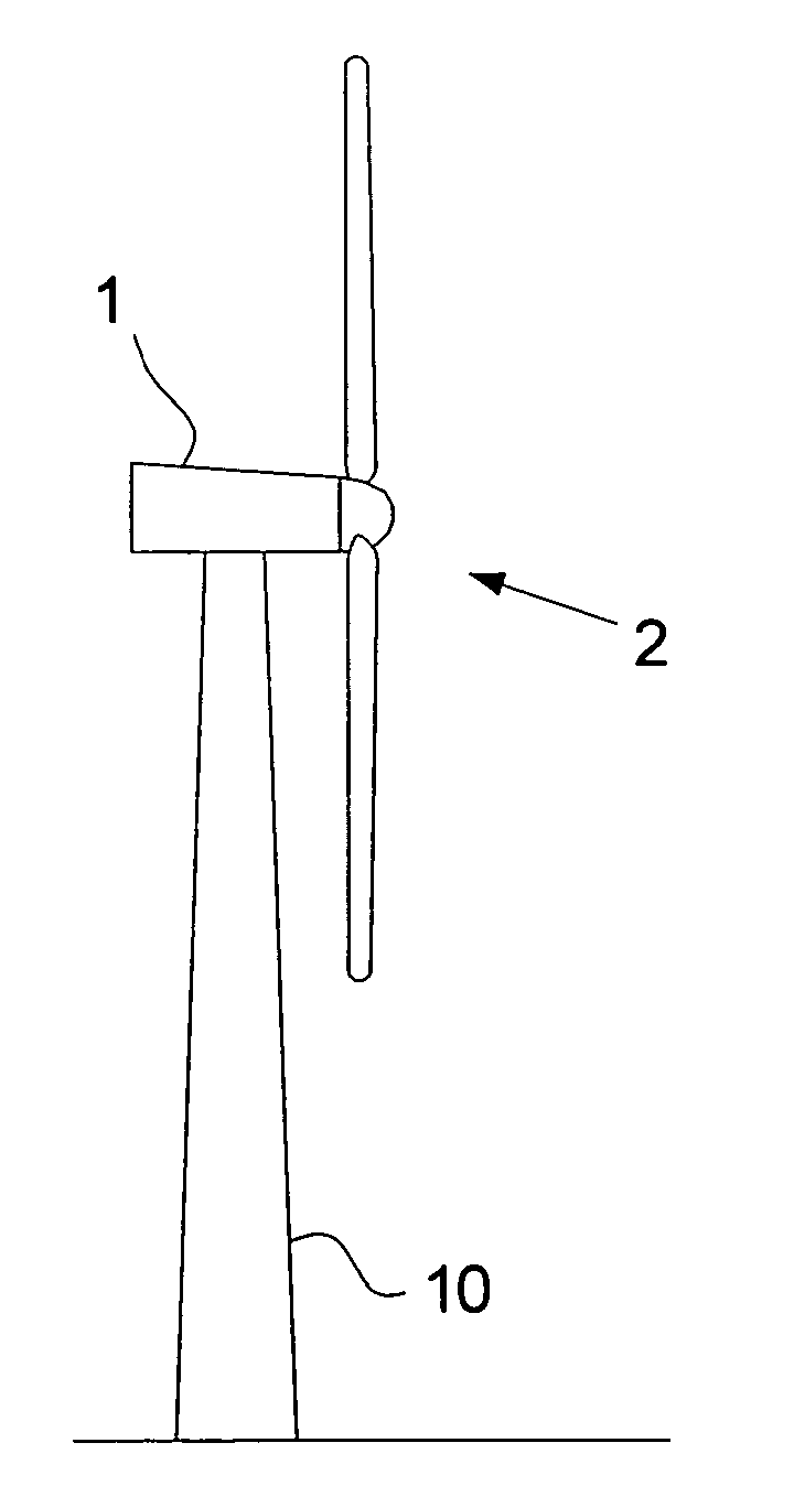
[0077]FIG. 1a illustrates a typical wind turbine. The wind turbine comprises a tower 10 founded to the ground by means of a foundation. The tower 10 carries a nacelle 1 and a rotor 2.

[0078]Today, most modern wind turbine towers are conical tubular steel towers.

[0079]FIG. 1b shows the cross section of ...


PUM


Abstract

A method of mounting elements in a wind turbine tower, whereby the elements are partly or completely attached to the wind turbine tower by means of magnetic attraction forces. Wind turbine suspension units may be attached to the wind turbine tower, preferably completely or partly to the inner wall by means of magnetic attraction forces, which prevent structure-weakening attachments to the tower or part of the tower.

Description

CROSS-REFERENCE TO RELATED APPLICATION[0001]This application is a continuation of U.S. patent application Ser. No. 10 / 157,286 filed on 29 May 2002 which claims priority to Danish Patent Application No. 2002 00178 filed on 6 Feb. 2002, both of which said applications are incorporated herein by reference in their entirety.TECHNICAL FIELD OF THE INVENTION[0002]The present invention relates to a method of mounting elements in a wind turbine tower.BRIEF DISCUSSION OF RELATED ART[0003]Typically, wind turbine towers carry the nacelle and the rotor of a wind turbine in order to allow for the desired rotation of the rotor and to raise the rotor into a position as far as possible from the ground as wind speeds typically increase with the distance to the ground.[0004]A wind turbine tower may be constructed according to several different principles, e.g. as tubular steel towers, lattice towers, or even concrete towers.[0005]Most large wind turbines are delivered with tubular steel towers manufa...

Claims


Application Information

Patent Timeline
IPC IPC(8): F03D11/04
CPCE04H12/085F03D11/04Y02E10/728F05B2260/302Y02E10/726F05B2240/912F03D13/20Y02E10/72E04B1/1903E04H12/00E04H12/342
Inventor OLLGAARD, BORGE
Owner VESTAS WIND SYST AS
Learn More