Image forming apparatus

an image forming and electrographic technology, applied in the field of electrographic image forming apparatus, can solve the problems of inconsistency of density, scattering of toner, inconsistency of density, etc., and achieve the effect of preventing toner scattering

Inactive Publication Date: 2008-06-19
SHARP KK
View PDF8 Cites 14 Cited by
  • Summary
  • Abstract
  • Description
  • Claims
  • Application Information

AI Technical Summary

Benefits of technology

[0013]The present invention is accomplished in view of the aforementioned problem. An object of the present invention is to prevent toner scattering and image inconsistency in an image forming apparatus in which development is carried out with columnar toner.
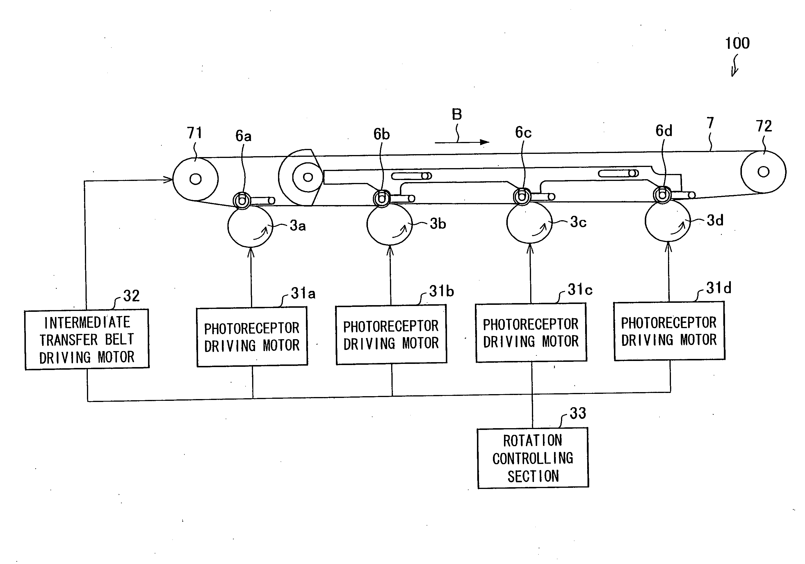
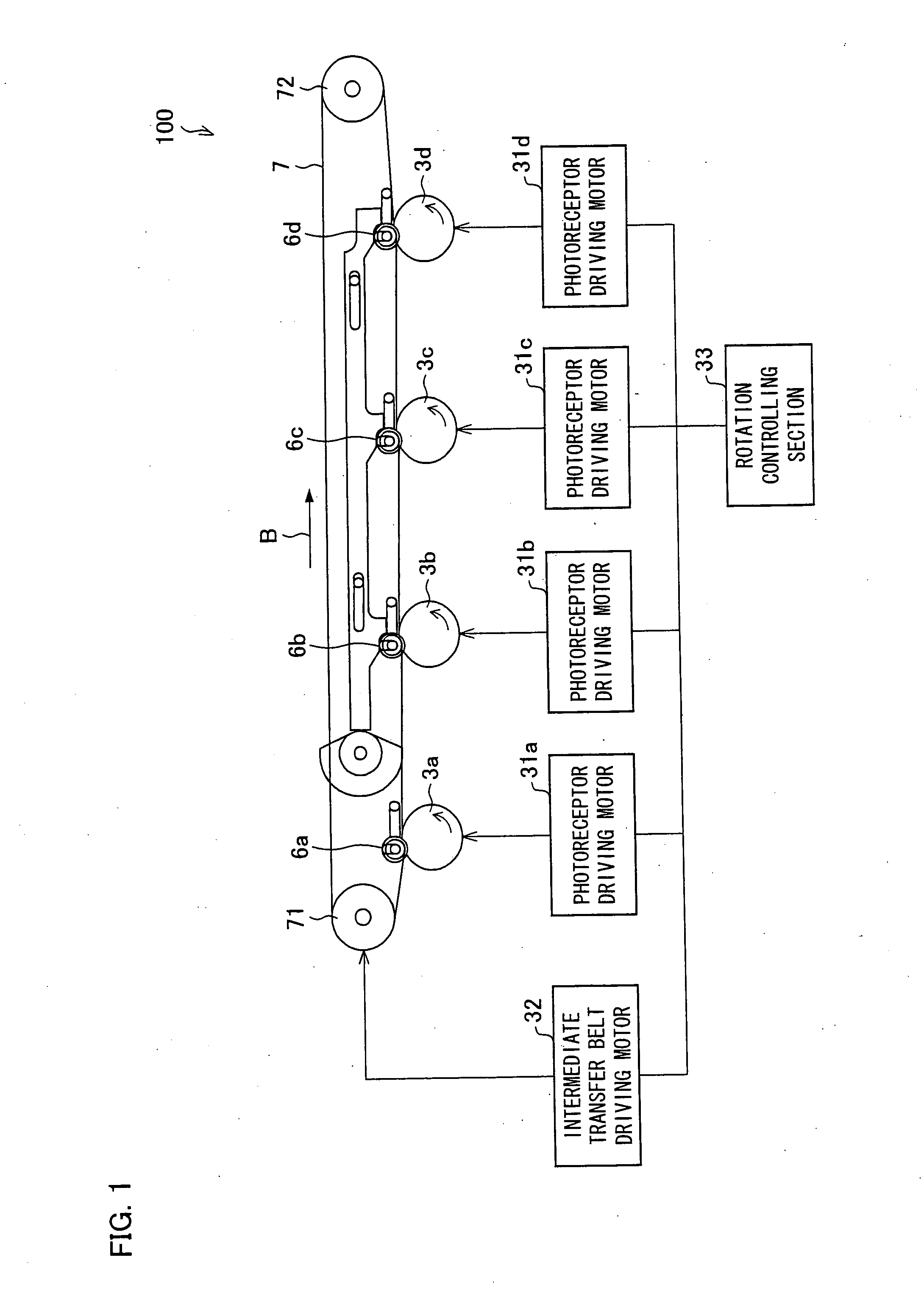
[0015]With this arrangement, in which the image bearing member and the image transfer body have different moving speeds at a contact position where they are in contact with each other, a rubbing force is caused between the image bearing member and the image transfer body. The rubbing force orients longitudinal directions of particles of the columnar toner along the main scanning direction (a direction vertical to a rotation direction). This allows the toner particles to attach with each other with a greater contact area, thereby attaining a greater coagulation between the toner particles. This prevents the toner scattering. Moreover, this prevents gap formation between the toner particles. This prevents density inconsistency in a transferred toner image.
[0016]The use of the columnar toner provides (a) stable image density, (b) better control over color density (gradation), (c) higher resolution, (d) prevention of photographic fog and or prevention of dusts (dots in white space) in transferring, (e) prevention of filming a developing roller or photoreceptor with toner particles, and the other effects.

Problems solved by technology

This would result in inconsistency of density due to spaces formed between the randomly-oriented toner particles, or would cause scattering of the toner particles.
This would cause scattering of toner before fixation, or inconsistency of density after the fixation.
However, they do not consider the use of the columnar toner and cannot enjoy the advantages (a) to (e) provided by the use of the columnar toner in the image forming apparatus.
However, it does not consider the use of the columnar toner and cannot enjoy the advantages (a) to (e) provided by the use of the columnar toner in the image forming apparatus.

Method used


Image

  • Image forming apparatus
  • Image forming apparatus
  • Image forming apparatus

Examples


embodiment 2

[0075]Another embodiment of the present invention is described below. For the sake of easy explanation, members having the same functions as those in the Embodiment 1 are labeled in the same manner and their explanation is omitted here.

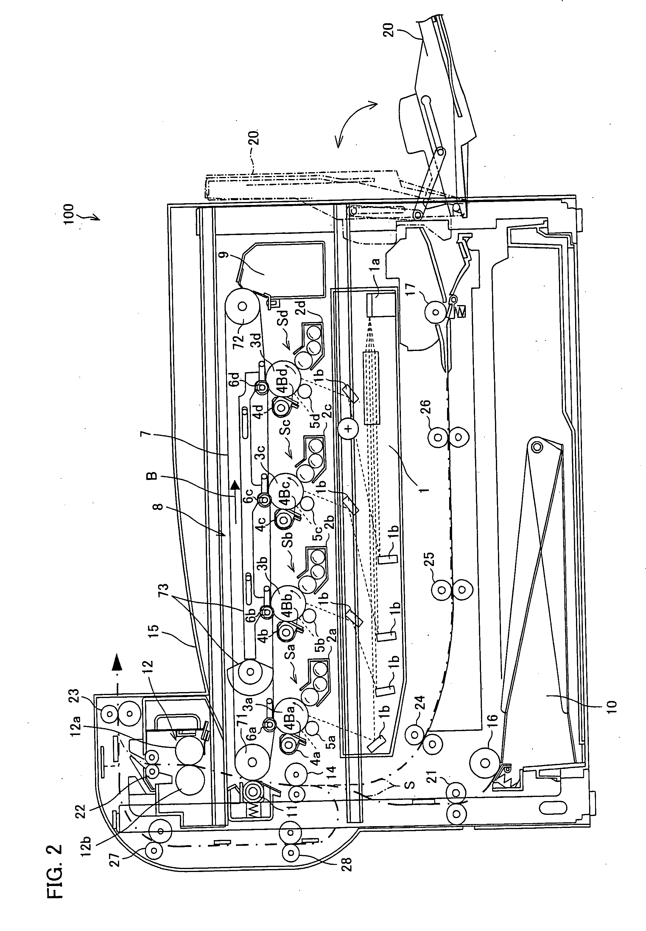
[0076]FIG. 8 is an explanatory view illustrating a structure of an image forming apparatus 100c according to the present embodiment. As illustrated in FIG. 8, the image forming apparatus 100c has the same configuration as the image forming apparatus 100 (see FIG. 2) in Embodiment 1 and further includes a transfer control section 61, transfer voltage generating section 62a to 62d, a DC (direct current) power source 63, and an AC (alternating current) power source 64.

[0077]The DC power source 63 supplies a DC potential to the transfer voltage generating sections 62a and 62b. The AC power source 64 supplies an AC potential to the transfer voltage generating sections 62a and 62b.

[0078]The transfer voltage generating sections 62a to 62d respectively gener...


PUM


Abstract

In an image forming apparatus in which a visual image on a photosensitive drum is developed with columnar toner, and the developed toner image is transferred from the photosensitive drum to an intermediate transfer belt, a moving speed of the photosensitive drum and a moving speed of the intermediate transfer belt are different at a contact position (transfer nip section) where the photosensitive drum and the intermediate transfer belt are in contact. With this arrangement, toner scattering, nonuniform image etc. can be reduced in the image forming apparatus, in which the development is carried out with columnar toner.

Description

[0001]This Nonprovisional application claims priority under 35 U.S.C. § 119(a) on Patent Applications No. 336287 / 2006 filed in Japan on Dec. 13, 2006, and No. 311630 / 2007, filed in Japan on Nov. 30, 2007, the entire contents of which are hereby incorporated by reference.FIELD OF THE INVENTION[0002]The present invention relates to an electrophotographic image forming apparatus, especially to an image forming apparatus, which performs development with columnar toner.BACKGROUND OF THE INVENTION[0003]An image forming apparatus using columnar toner has been proposed conventionally. The columnar toner is advantageous in that the toner has uniform diameter easily, the toner can be produced with a high yield, and the toner forms an image with even thickness easily. With these advantageous properties, the columnar toner is expected to attain (a) stable image density, (b) better control over color density (gradation), (c) higher resolution, (d) prevention of photographic fog and or prevention...

Claims


Application Information

Patent Timeline
IPC IPC(8): G03G15/16
CPCG03G15/08G03G15/161G03G15/5008G03G15/1605G03G2215/0602G03G2215/1623G03G2215/00075
Inventor TOIZUMI, KIYOSHIHAYASHI, RIKA
Owner SHARP KK
Why Eureka
Try Eureka