
Furniture hinge with a damping device

Inactive Publication Date: 2008-06-19
LIBERTY HARDWARE MFG
View PDF8 Cites 4 Cited by
  • Summary
  • Abstract
  • Description
  • Claims
  • Application Information

AI Technical Summary

Benefits of technology

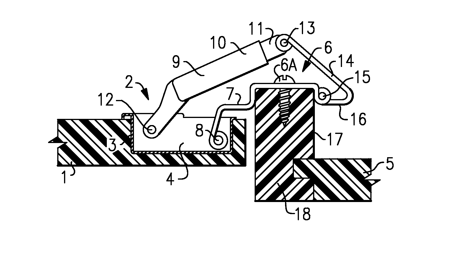
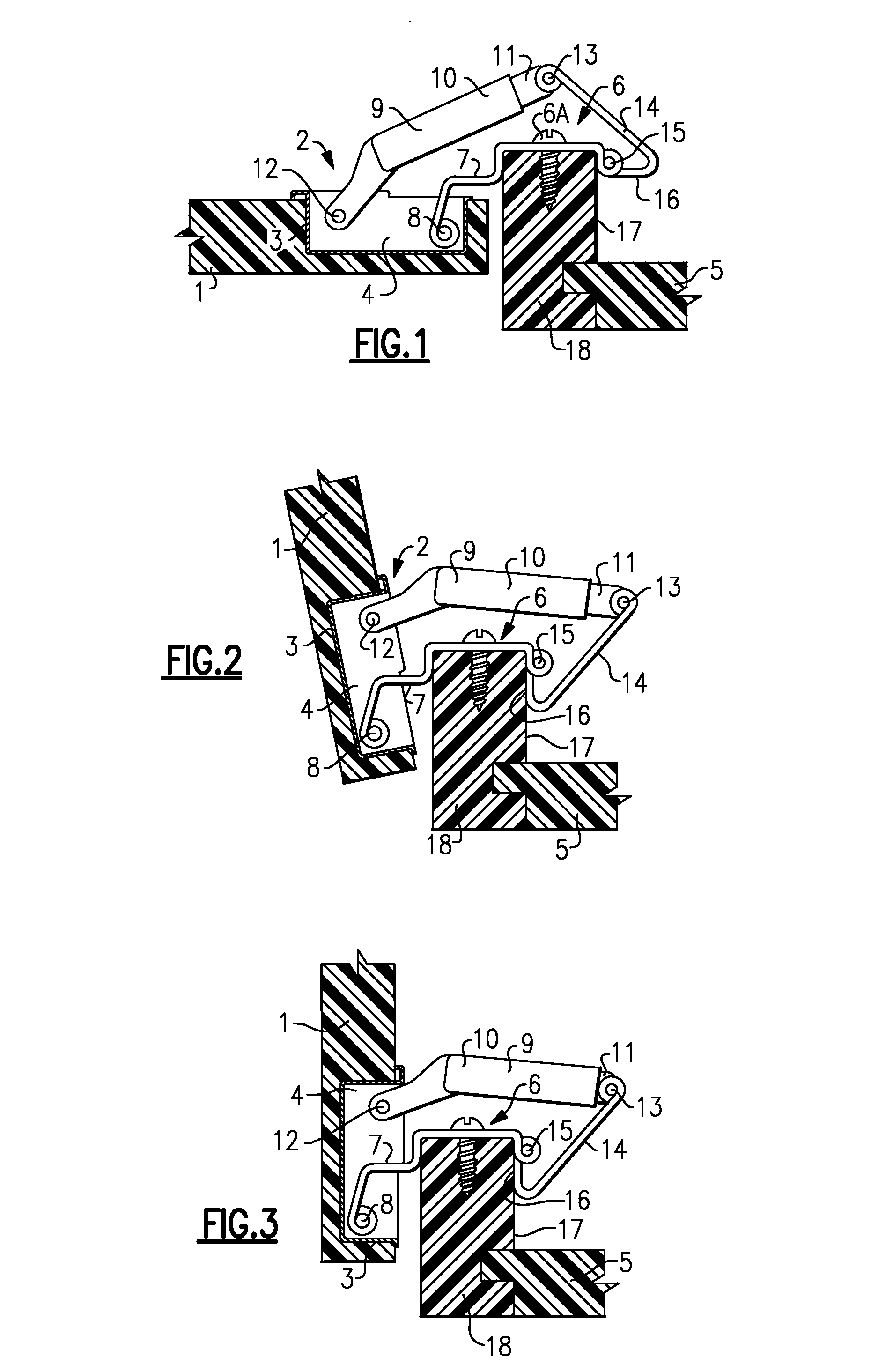
[0007]In contrast to a rotary damping device, the damping cylinder, which has a joint on each of its two ends, exerts a damping action not in the course of a pivot movement, but during a linear change between the two joints. The two-link damping chain, consisting of the damping cylinder and the damping guidance device, moves without a damping effect during the larger portion of the closing movement of the furniture hinge. When the pivot stop for the damping guidance device becomes effective toward the end of the closing movement of the furniture hinge, the damping cylinder becomes fixed relative to the body fastening element. From this pivot movement onward, the joint connecting the damping guide device with the damping cylinder constitutes a fixed point relative the body fastening element, which supports the damping cylinder. Then, in the course of the continued closing movement of the furniture door, the effective length of the damping cylinder is reduced, which produces a damping force counteracting the closing movement.

Problems solved by technology

Closing forces generated when closing a furniture door cause the furniture door to impact the furniture body.
Closing forces are particularly high when rapidly closing the furniture door.
However, only a small amount of closing force is absorbed with the bumpers due to the thickness of the bumper.
An undesirable impact noise is generated in such an arrangement because of the impact of the door stop element on the free end of the piston rod.
This complicates and slows pivoting ability of the furniture door during the first portion of the closing movement.
Also, the structure of such hinges is comparatively large.

Method used


Image

  • Furniture hinge with a damping device
  • Furniture hinge with a damping device
  • Furniture hinge with a damping device

Examples


Embodiment Construction

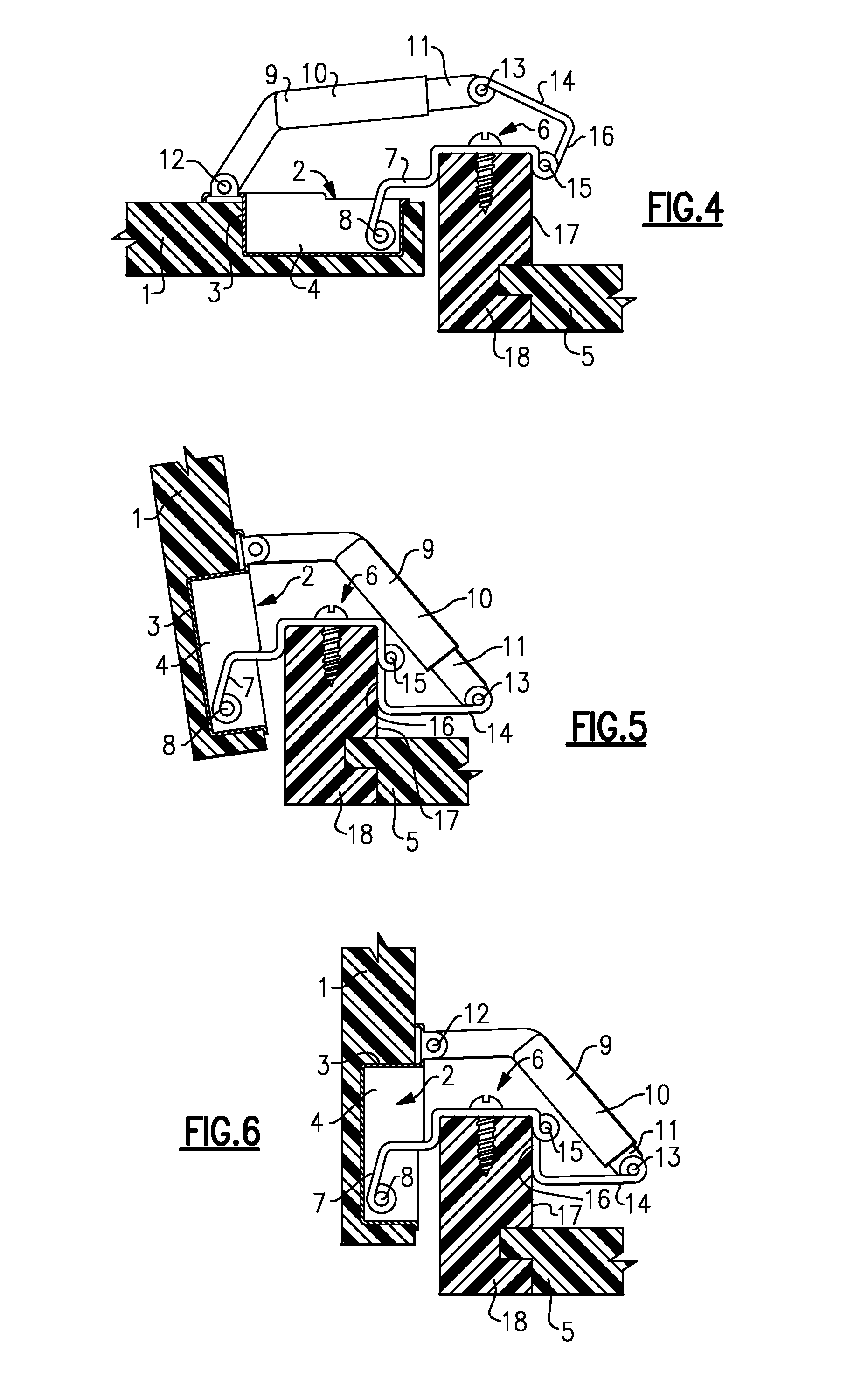
[0029]Referring to FIGS. 1 to 3, an example furniture hinge includes a door fastening element 2 secured to a furniture door 1 through an insertion cup 4, which can be introduced into a cup bore 3 of the furniture door 1.

[0030]A body fastening element 6 secures to a furniture body 5 with a fastening screw 6a. In this example, the body fastening element 6 is arranged relative the furniture body 5 in a “face-frame” type of construction. A support arm 7, a type of pivot arm, rigidly fastens to the furniture body 5, and is seated on the door fastening element 2 on a joint 8 inside the insertion cup 4.

[0031]An example damping device includes a linearly movable damping cylinder 9 having a damping piston received in a linearly movable manner within a cylinder housing 10. A damping medium (such as a fluid or gas) flowing between damping bores in the course of the piston movement, causes damping of the piston movement. The piston (not shown) connects to a piston rod 11 extending from the cyli...


PUM


Abstract

An example furniture hinge includes a damping device having a linearly movable damping cylinder, which is hingably connected to a door stop element and a damping guidance element. When closing the furniture hinge, the damping guide element can be pivoted against a pivot stop on the body fastening element.

Description

CROSS REFERENCE TO RELATED APPLICATIONS[0001]This application claims priority to German Patent Application No. 10 2006 059 247.6, which was filed on 15 Dec. 2006.BACKGROUND OF THE INVENTION[0002]The invention relates to a furniture hinge with a door stop element and dampening device.[0003]Closing forces generated when closing a furniture door cause the furniture door to impact the furniture body. Closing forces are particularly high when rapidly closing the furniture door. For reducing the shock and the noise associated with closing forces, it is known to install bumpers on the furniture body or on the furniture door. However, only a small amount of closing force is absorbed with the bumpers due to the thickness of the bumper.[0004]In other known furniture hinges such as the furniture hinge described in United States Patent Application No. 2004 / 0205935 A1, a piston rod of a damping cylinder attaches to a furniture stop element projecting toward the furniture door. When closing the f...

Claims


Application Information

Patent Timeline
IPC IPC(8): E05D7/04E05D11/08
CPCE05D3/142E05F5/006E05F5/10E05Y2201/21E05Y2201/256Y10T16/54021E05Y2600/456E05Y2900/20Y10T16/532Y10T16/5383E05Y2201/264
Inventor LAUTENSCHLAGER, HORST
Owner LIBERTY HARDWARE MFG
Learn More