
Motor

Inactive Publication Date: 2008-06-12
LG ELECTRONICS INC
View PDF33 Cites 10 Cited by
  • Summary
  • Abstract
  • Description
  • Claims
  • Application Information

AI Technical Summary

Benefits of technology

[0012]An advantage of the present invention is to provide a motor capable of being smoothly fabricated with a compact exterior by reducing a motor mounting space, such that the extent of motor applicability may be broad.
[0013]Another advantage of the present invention is to provide a motor which enhances efficiency to minimize electricity loss.
[0014]A further advantage of the present invention is to provide a motor which can control its rotational speed or torque to enhance reliability and durability.
[0015]More specifically, according to the present invention, cogging torque is reduced to enhance the efficiency of the motor such that the motor may be controlled more smoothly.
[0016]Additional advantages, and features of the invention will be set forth in part in the description which follows and in part will become apparent to those having ordinary skill in the art upon examination of the following or may be learned from practice of the invention. These and other advantages of the invention may be realized and attained by the structure particularly pointed out in the written description and claims hereof as well as the appended drawings.
[0017]To achieve these and other advantages and in accordance with the purpose of the invention, as embodied and broadly described herein, a motor comprising: a stator core, which forms a magnetic path, having a plurality of tooth parts along a circumferential direction; a tooth provided in each of the plurality of tooth parts, such that a coil is wind around the tooth; and an extension part alternating between one of the plurality of tooth parts along a circumferential direction of the stator core, such that the extension part extends convexly in an inner radial direction.

Problems solved by technology

When the rotor is rotating, the shading coil is not needed and causes electricity loss.
However, commonly the shading coil motor consumes and loses electricity a lot.
Also, it is difficult to control the shading coil motor and there is a further disadvantage of its large size.

Method used


Image

  • Motor
  • Motor
  • Motor

Examples


Embodiment Construction

[0028]Reference will now be made in detail to the preferred embodiments of the present invention, examples of which are illustrated in the accompanying drawings. Wherever possible, the same reference numbers will be used throughout the drawings to refer to the same like parts.

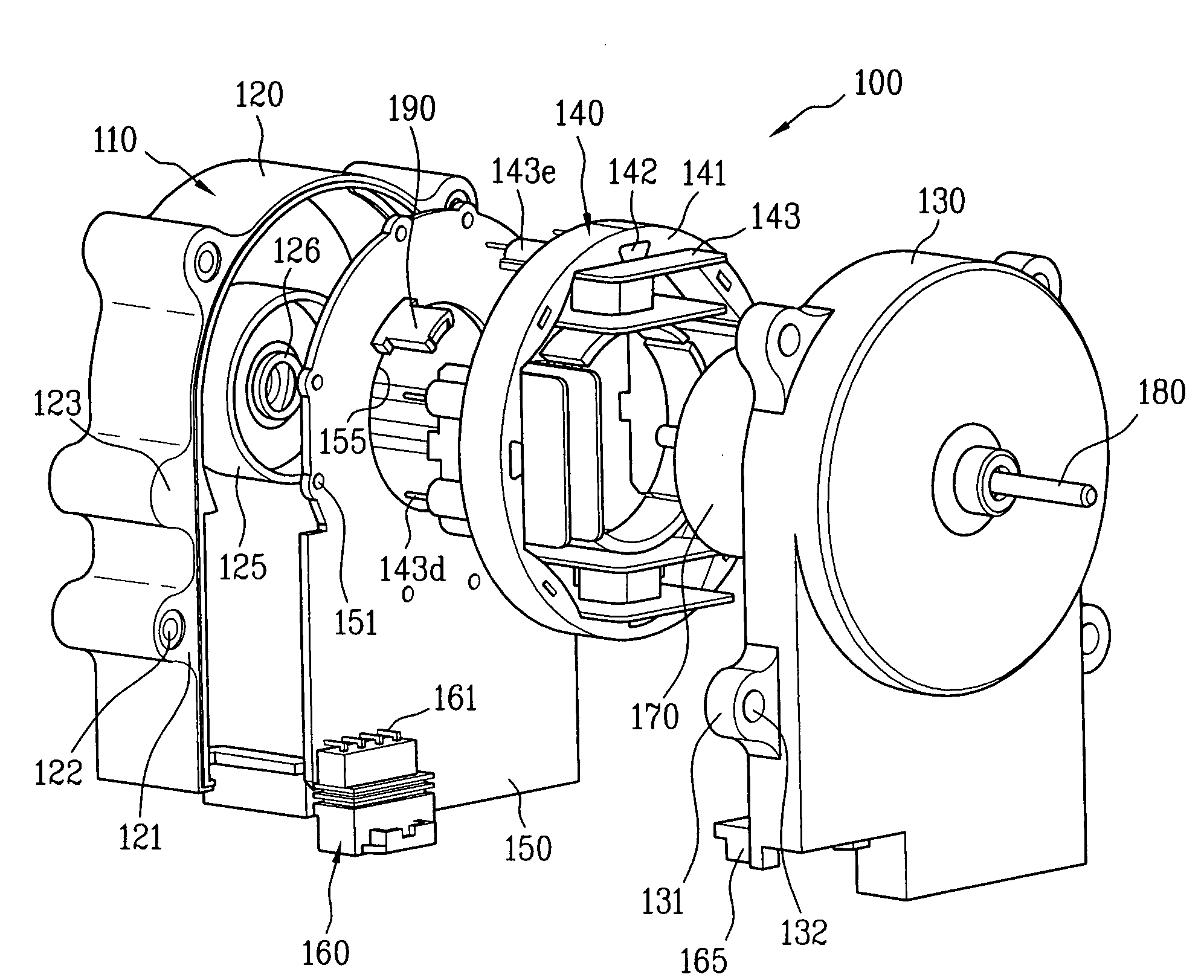
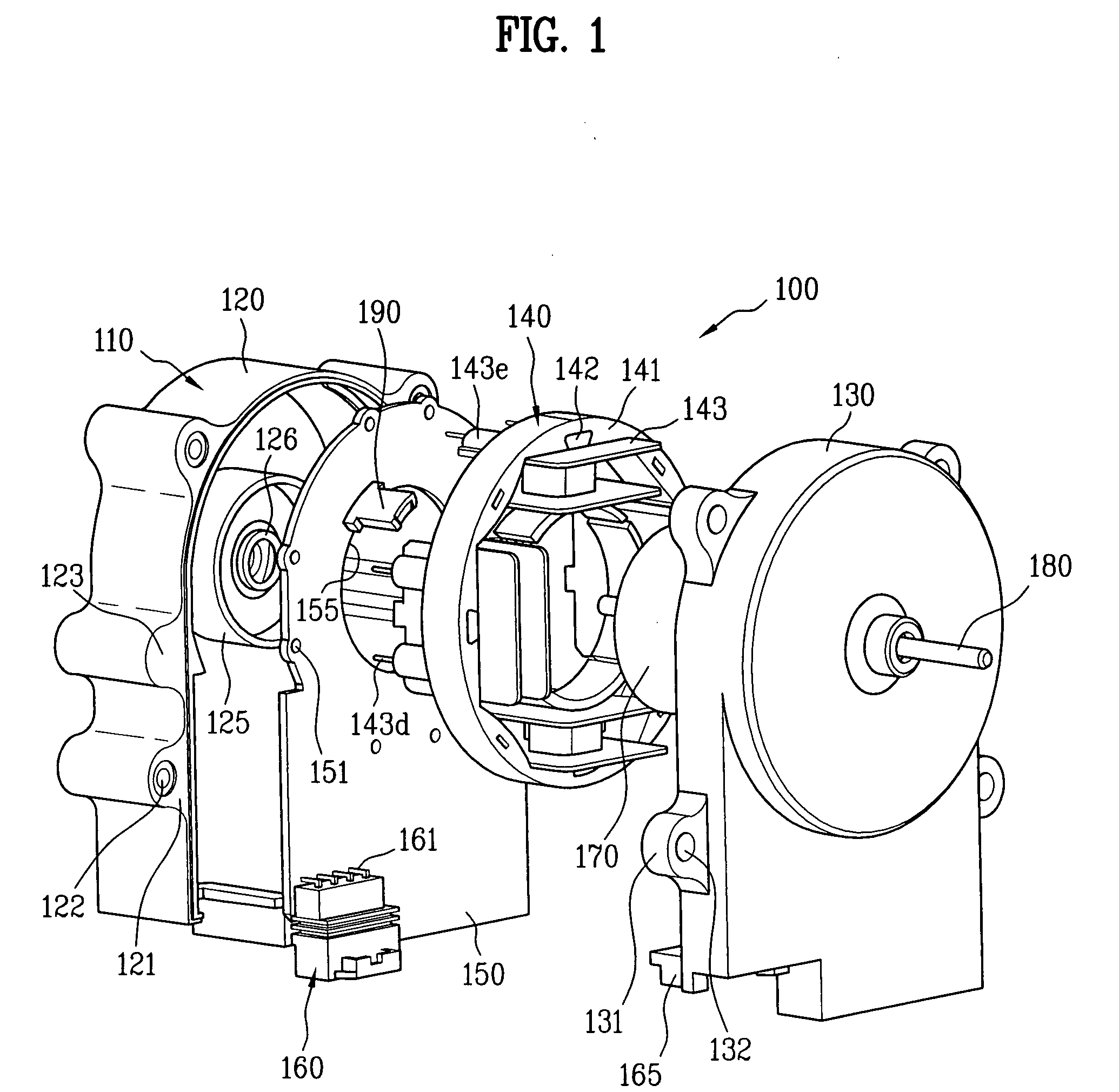
[0029]FIG. 1 is an exploded perspective view of a motor 100 according to the present invention.

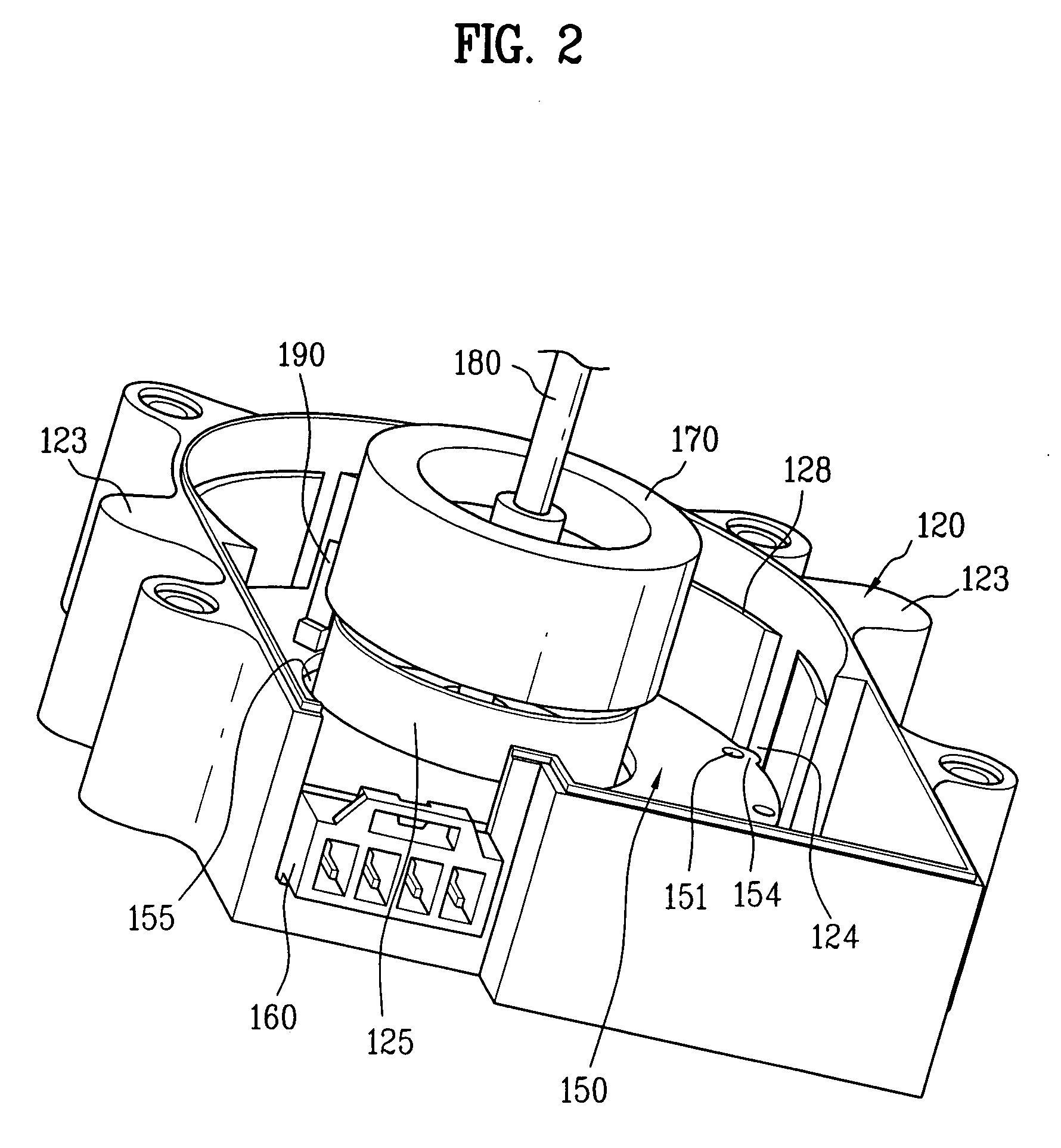
[0030]As shown in FIG. 1, a motor 100 of the present invention includes a bracket 110 , a printed circuit board (PCB)150, a stator 140, a rotor 170 and a shaft 180. The bracket 110 defines an exterior of the motor. The PCB 150 is held within the bracket 110 and an electric pattern (not shown). Also, various elements (not shown) are mounted on the PCB 150.

[0031]The bracket 110 includes a lower bracket 120 and an upper bracket 130. The lower and upper brackets 120 and the 130 are coupled to each other to hold various components therebetween. To couple the lower and upper brackets 120 and 130 to each other, a fastening b...


PUM


Abstract

A motor includes a stator core that forms a magnetic path and has a plurality of tooth parts along a circumferential direction; a tooth provided in each tooth part to wind a coil there around; and an extension part alternated with the tooth part along a circumferential direction of the stator core, convexly extending to an inner radial direction.

Description

[0001]This application claims the benefit of the Patent Korean Application Nos. 10-2006-0122998, 10-2006-0122999, 10-2006-0123000 and 10-2006-0123001 filed on Dec. 6, 2006, and all of which are hereby incorporated by reference as if fully set forth herein.BACKGROUND OF THE INVENTION[0002]1. Field of the Invention[0003]The present invention relates to a motor, more particularly, to a motor easily fabricated and having enhanced efficiency and durability, which has a compact structure.[0004]2. Discussion of the Related Art[0005]Typically, a shading coil motor is incorporated into a refrigerator or a freezer as a fan motor. A shading coil, as well as, a main coil is wound around a stator in the shading coil motor.[0006]The shading coil is configured to start a rotor. The shading coil, together with the main coil, forms an oval shaped magnetic field to start a rotor. When the rotor is rotating, the shading coil is not needed and causes electricity loss.[0007]Moreover, auxiliary teeth sho...

Claims


Application Information

Patent Timeline
IPC IPC(8): H02K11/00H02K1/12H02K5/00H02K1/28H02K1/18
CPCH02K1/148H02K1/185H02K11/0073H02K5/225H02K3/522H02K11/33
Inventor LEE, HO JAE
Owner LG ELECTRONICS INC
Learn More