
Turbocharged internal combustion engine system

a turbocharged internal combustion engine and turbocharger technology, applied in the direction of electric control, process and machine control, instruments, etc., can solve the problems of increasing the weight of ice charge, and achieve the effect of increasing the compressor surge limit, accelerating the compressor speed, and speeding up the compressor speed

Inactive Publication Date: 2008-06-05
AGWEST
View PDF35 Cites 81 Cited by
  • Summary
  • Abstract
  • Description
  • Claims
  • Application Information

AI Technical Summary

Benefits of technology

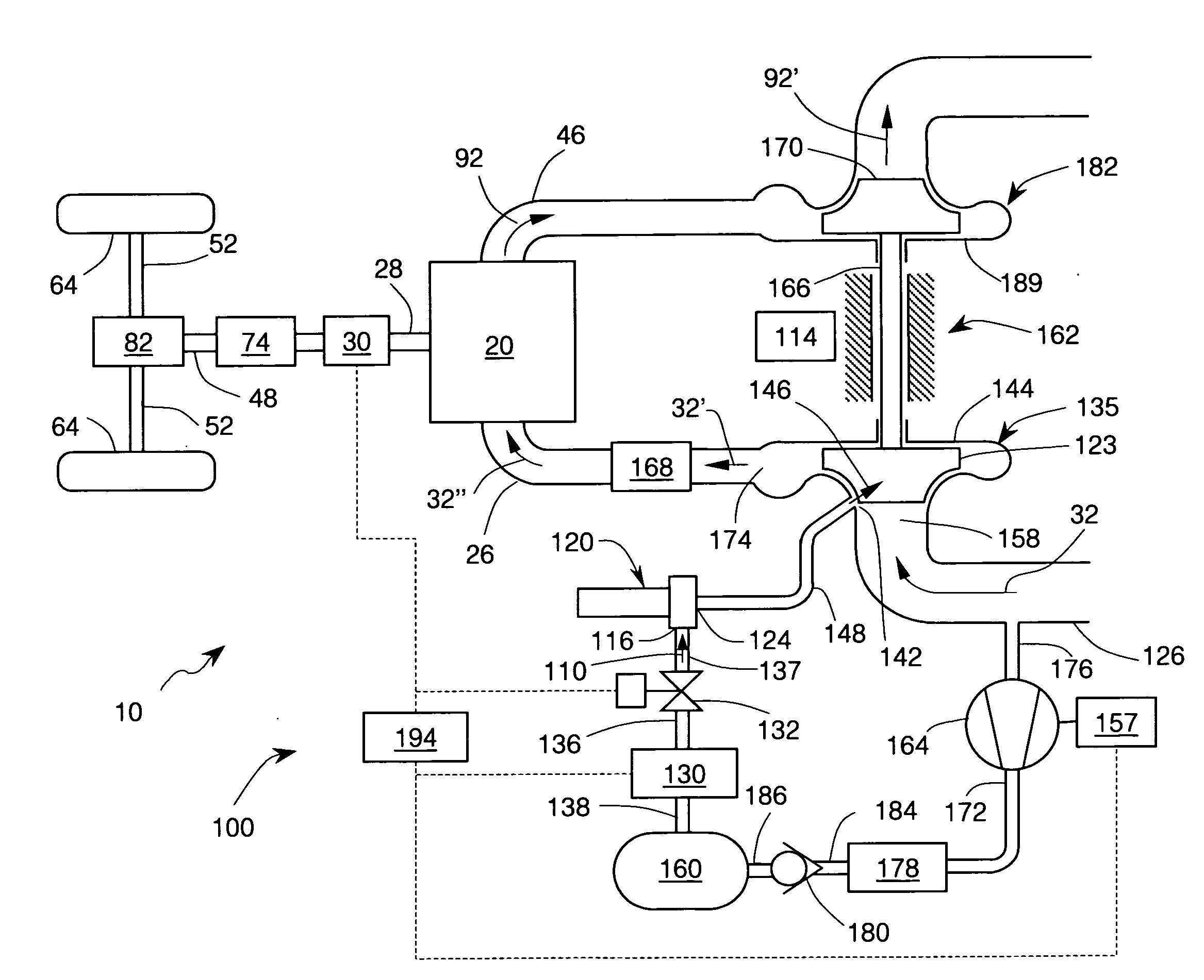
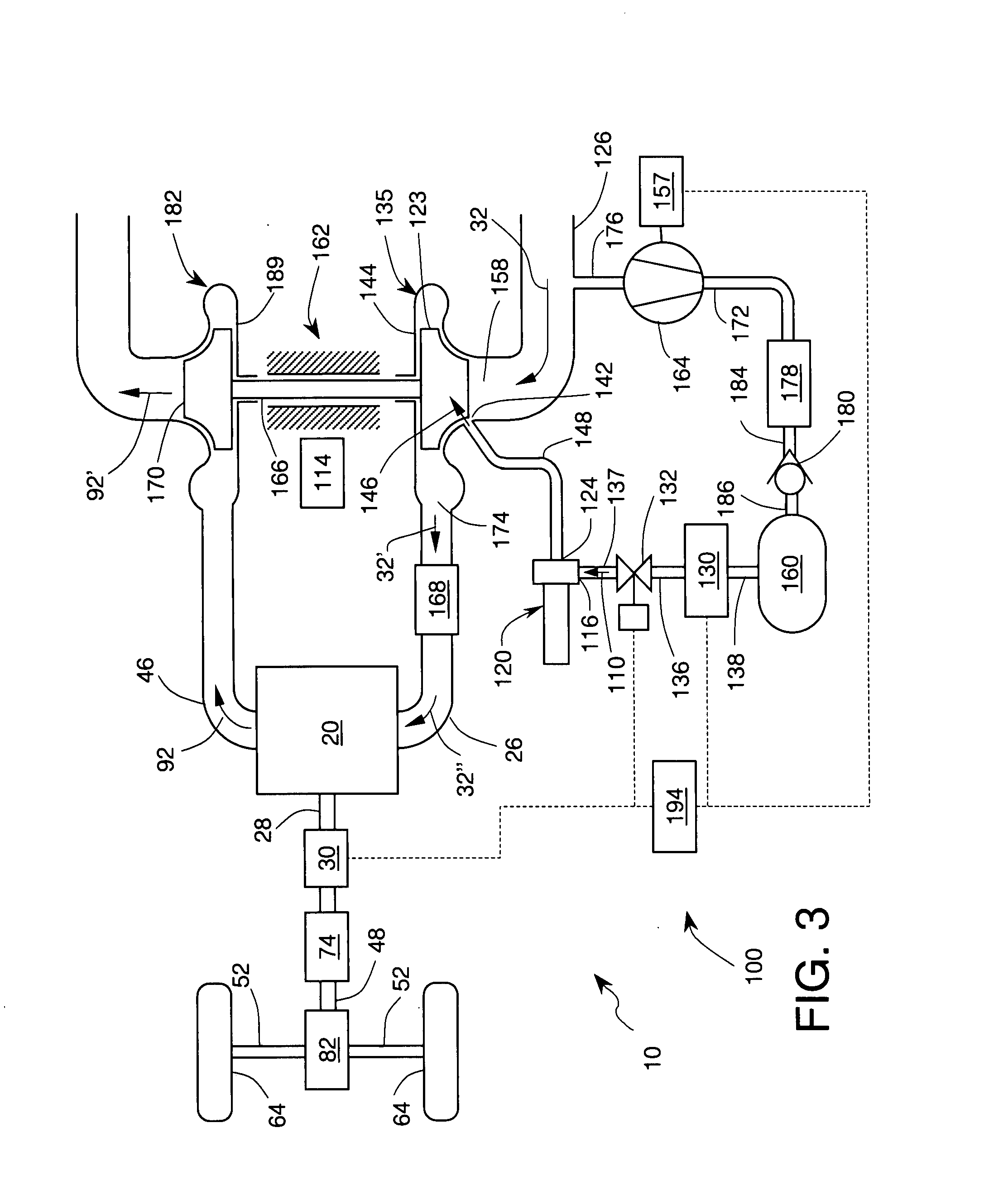
[0011]The present invention provides a turbocharged ICE system wherein the turbocharger assembly comprises a vortex tube that supplies cold, dense air to the ICE intake. When such cold air is supplied to a turbocharger compressor in the ICE intake, it may beneficially increase the compressor surge limit, cool the compressor blades, and accelerate the compressor speed. Faster compressor speed is conducive to generating higher charge pressure. In addition to increasing the charge pressure, injection of cold dense air may cool the engine intake air, which may further increase the weight of ICE charge and thus enable the ICE to produce more output power. Injection of cold air in the form of high-velocity jet onto compressor impeller may also enhance transfer of kinetic energy from the jet to the impeller and promote further increase in impeller speed. Cold air from the vortex tube may be also injected into the flow of intake air downstream of the compressor impeller either into the compressor diffuser or into the engine intake duct. In particular, cold air may be injected into the intake duct as one or more high velocity jets arranged to entrain and pump engine intake air, thereby increasing charge air density both by compression and by cooling. Suitable cold air injector may be a nozzle adapted for subsonic, sonic, or supersonic flow regime. Furthermore, the injector in the intake duct may be a driving nozzle which may also include lobes to enhance mixing. The compressed air for operation of the vortex tube may be obtained from the turbocharger compressor output flow or it may it may be supplied from an auxiliary air source. Suitable auxiliary air source may include an auxiliary compressor and / or an air tank.

Problems solved by technology

The resulting intake air mixture is colder and denser, which results in increased weight of ICE charge.

Method used


Image

  • Turbocharged internal combustion engine system
  • Turbocharged internal combustion engine system
  • Turbocharged internal combustion engine system

Examples


Embodiment Construction

[0033]Selected embodiments of the present invention will now be explained with reference to drawings. In the drawings, identical components are provided with identical reference symbols. It will be apparent to those skilled in the art from this disclosure that the following descriptions of the embodiments of the present invention are merely exemplary in nature and are in no way intended to limit the invention, its application, or uses.

[0034]Referring to FIG. 3, there is shown a turbocharged internal combustion engine (ICE) system 10 in accordance with one embodiment of the subject invention. The ICE system 10 comprises an ICE 20 and a turbocharger assembly 100. The ICE 20 has at least one combustion chamber fluidly coupled to an intake duct 26 to receive intake air therefrom and to an exhaust duct 46 to discharge exhaust gases thereinto. The type of ICE 20 may be either a compression ignition (diesel), a fuel injected spark ignition, carbureted spark ignition, or homogeneous charge ...


PUM


Abstract

The present invention relates to a turbocharged internal combustion engine (ICE) system having fast response to increased power demand and reduced response time lag. The system includes a vortex tube for delivering cold air into the turbocharger compressor where it may be used to cool the impeller, and / or accelerate the impeller rotational speed, and / or favorably shift the compressor surge line at low speeds and high loads. Cold air from the vortex tube may be also used to operate an ejector pump in the intake duct which further compresses intake air and increases engine charge weight during periods of high power demand. In addition to increasing engine output power, delivery of cold air into engine intake also reduces engine pre-ignition (knocking) thereby reducing emissions. The invention also relates to a method for operating a turbocharged internal combustion engine.

Description

CROSS-REFERENCE TO RELATED APPLICATIONS:[0001]This patent application is a continuation-in-part patent application of: U.S. Ser. No. 11 / 655,441 filed on Jan. 19, 2007 and entitled SUPERCHARGED INTERNAL COMBUSTION ENGINE SYSTEM; U.S. Ser. No. 11 / 443,424 filed on May 29, 2006 and entitled SUPERCHARGED INTERNAL COMBUSTION ENGINE; and U.S. Ser. No. 11 / 389,795 filed on Mar. 27, 2006 and entitled SUPERCHARGED INTERNAL COMBUSTION ENGINE, the entire contents of all of which are hereby expressly incorporated by reference.FIELD OF THE INVENTION[0002]This invention relates generally to supercharged internal combustion engines and, more particularly, to compressors for superchargers capable of fast response to engine demand and delivering high boost during low engine speed.BACKGROUND OF THE INVENTION[0003]Turbocharging of Internal Combustion Engines: One of the long-term goals of the automotive manufacturers is to reduce fuel consumption and emissions of modem automotive vehicles powered by int...

Claims


Application Information

Patent Timeline
IPC IPC(8): F02D41/00
CPCF02B29/0412F02B29/0481F02B37/127F02B37/164Y02T10/144F02B39/10F02D41/0007F02D41/10Y02T10/146F02B37/24F04D27/0238F02B37/162Y02T10/12
Inventor VETROVEC, JAN
Owner AGWEST
Learn More