
Method and apparatus for acquiring magnetic resonance imaging data

a magnetic resonance imaging and data acquisition technology, applied in the field of magnetic resonance imaging systems, can solve the problems of image artifacts, degrade overall image quality, and require longer than a minute to acquire sufficient data for an entire imag

Inactive Publication Date: 2008-06-05
GE MEDICAL SYST GLOBAL TECH CO LLC
View PDF3 Cites 17 Cited by
  • Summary
  • Abstract
  • Description
  • Claims
  • Application Information

AI Technical Summary

Problems solved by technology

However, for most other pulse sequences, acquisition of sufficient data for an entire image requires longer than a minute.
Patient motion during the image acquisition may therefore result in image artifacts, and / or may degrade overall image quality.
While the assumption of a stationary patient is usually valid for an EPI acquisition, it is not always reliable for longer acquisitions.
Some patients are able to remain reasonably still while a pulse sequence is being played out, however, motion may present a significant challenge in pediatric patients, trauma patients, or patients who are unable to follow instructions to remain still.

Method used


Image

  • Method and apparatus for acquiring magnetic resonance imaging data
  • Method and apparatus for acquiring magnetic resonance imaging data
  • Method and apparatus for acquiring magnetic resonance imaging data

Examples


Embodiment Construction

[0015]In the following detailed description, numerous specific details are set forth in order to provide a thorough understanding of embodiments. However it will be understood by those of ordinary skill in the art that the embodiments may be practiced without these specific details. In other instances, well-known methods, procedures, components and circuits have not been described in detail so as not to obscure the embodiments.

[0016]MRI data is typically collected in a Fourier space known in imaging as “k-space,” a reciprocal space connected to real space via a Fourier transform. Each line of MRI data in k-space corresponds to a MR signal that has been encoded with a particular spatial frequency and acquired and digitized. In accordance with embodiments, an offset vector and rotation matrix may be determined for each k-space line individually during the acquisition of MRI data. The ability to define different offset vectors and rotation matrices for each k-space line allows tracking...


PUM

PropertyMeasurementUnit
Larmor frequencyaaaaaaaaaa
frequencyaaaaaaaaaa
frequencyaaaaaaaaaa

Abstract

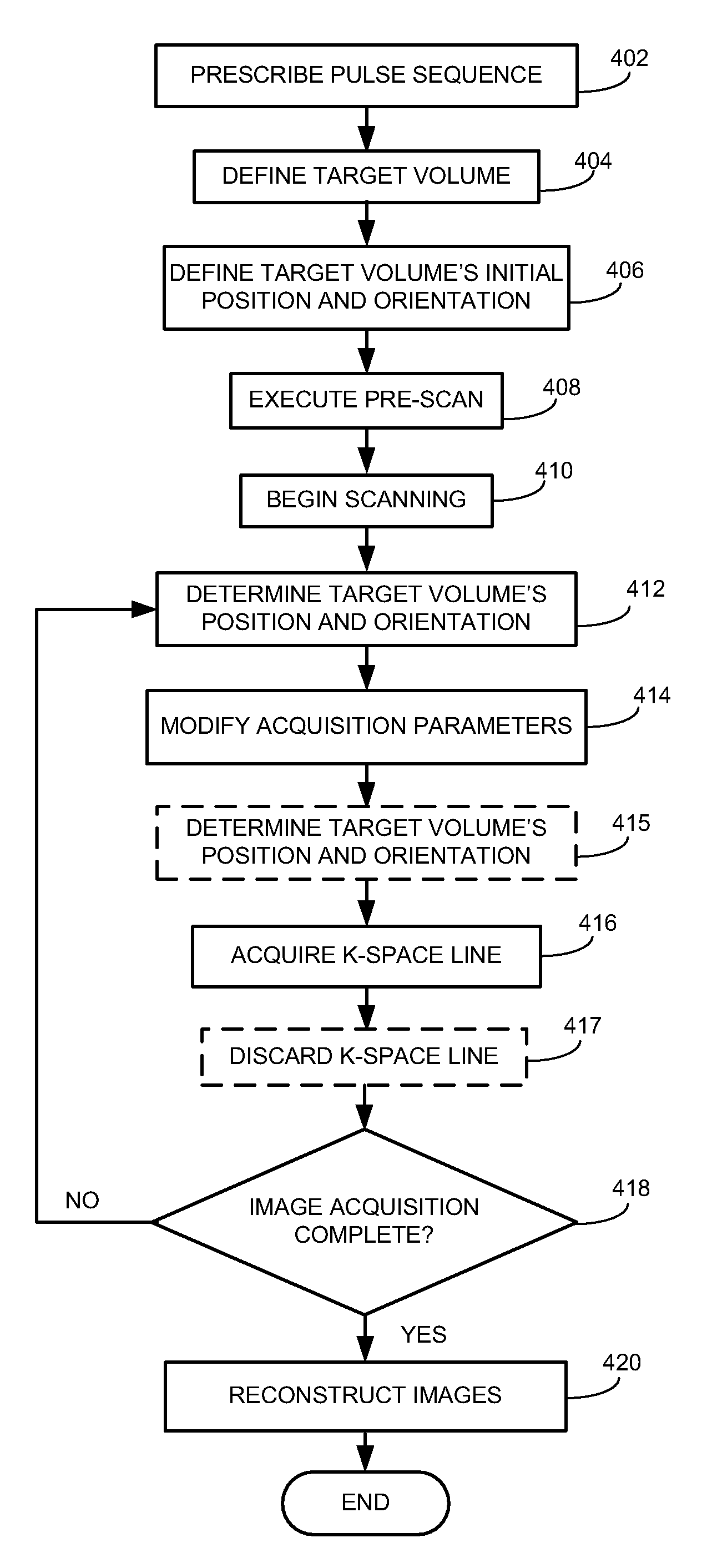
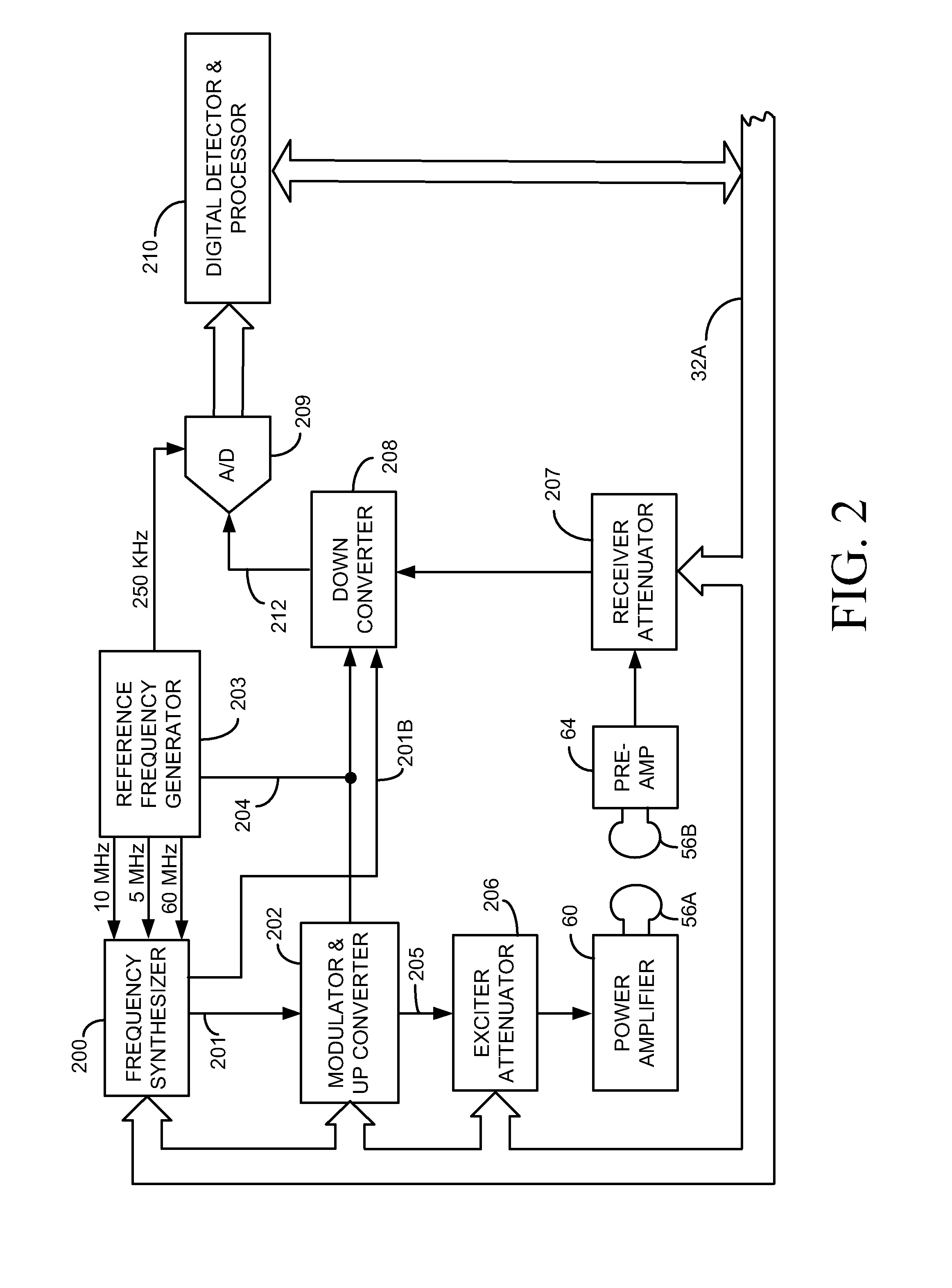
A method for generating a magnetic resonance image of a moving subject comprises tracking the position and orientation of a target volume and modifying acquisition parameters for each line of k-space data using current position and orientation information. By approximating the target volume as a rigid object, the current position and orientation is translated into an offset vector and a rotation which are used to modify the acquisition of each k-space line individually. The offset along a slice direction is compensated for by changing the transmit frequency. The offset along the frequency-encoding direction is compensated for by changing the frequency of a reference demodulation signal. The offset along the phase direction is compensated for by changing the phase of a reference demodulation signal, or by adding a phase into the line of k-space data after acquisition. The rotation is applied directly to the logical axes to change the angles between the logical axes and the physical axes of a magnetic resonance imaging system.

Description

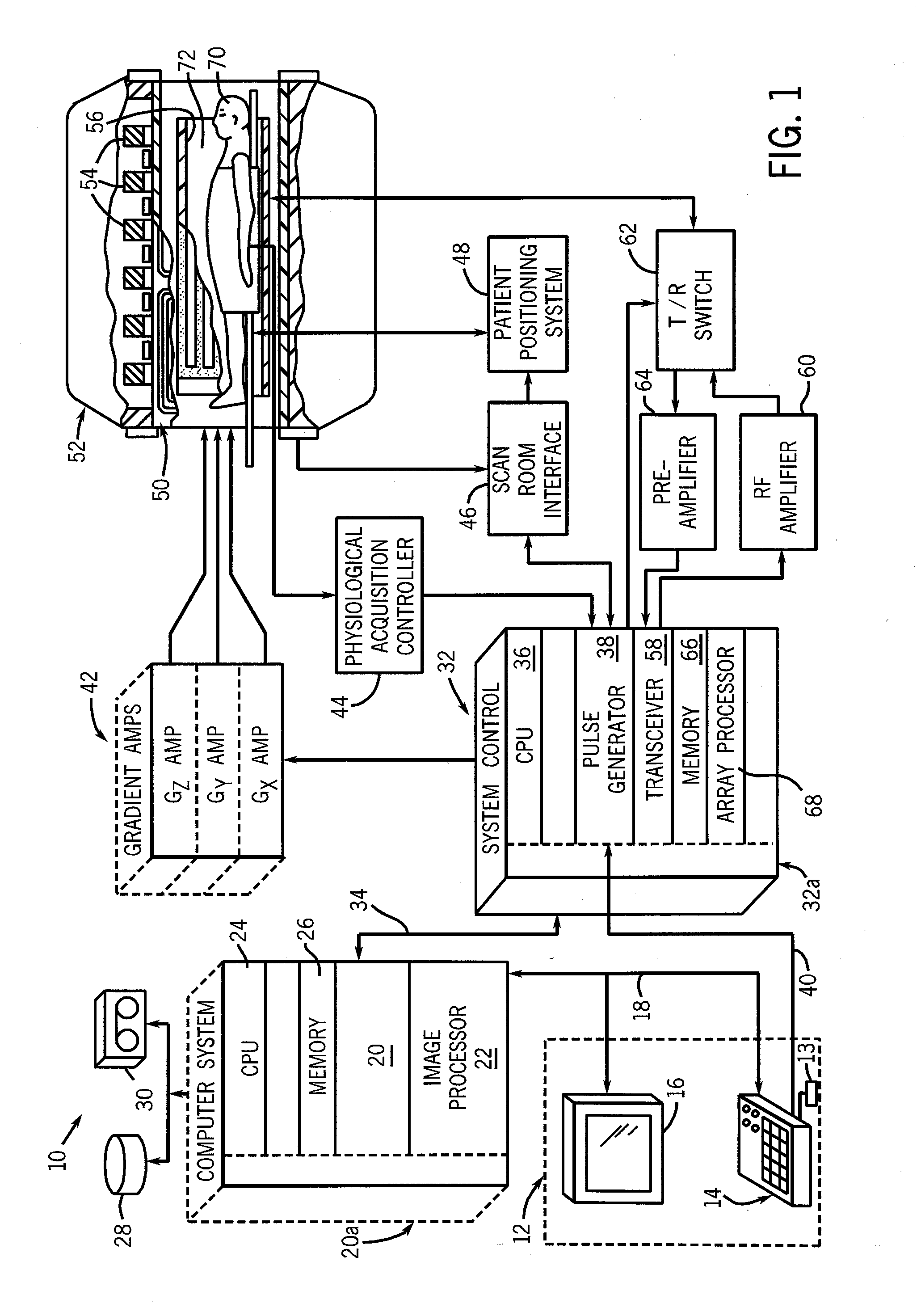
TECHNICAL FIELD[0001]The present invention relates generally to magnetic resonance imaging (MRI) systems and in particular, to a method and apparatus for acquiring magnetic resonance imaging data from a moving patient.BACKGROUND[0002]Magnetic resonance imaging (MRI) is a medical imaging modality that can create pictures of the inside of a human body without using x-rays or other ionizing radiation. MRI uses a powerful magnet to create a strong, uniform, static magnetic field (i.e., the “main magnetic field”). When a human body, or part of a human body, is placed in the main magnetic field, the nuclear spins that are associated with the hydrogen nuclei in tissue water become polarized. This means that the magnetic moments that are associated with these spins become preferentially aligned along the direction of the main magnetic field, resulting in a small net tissue magnetization along that axis (the “z axis”, by convention). An MRI system also comprises components called gradient co...

Claims


Application Information

Patent Timeline
Patent Type & Authority Applications(United States)
IPC IPC(8): G01N24/08
CPCG01R33/5673G01R33/56509
Inventor YAO, JIABIN
Owner GE MEDICAL SYST GLOBAL TECH CO LLC
Learn More