
Advanced control of severe fluid catalytic cracking process for maximizing propylene production from petroleum feedstock

Active Publication Date: 2008-06-05
SAUDI ARABIAN OIL CO
View PDF50 Cites 28 Cited by
  • Summary
  • Abstract
  • Description
  • Claims
  • Application Information

AI Technical Summary

Benefits of technology

[0016]As disclosed herein, a fluid catalytic cracking unit, appropriately modified in accordance with the teachings herein for optimum propylene production, can be utilized to produce light-fraction olefins. Utilization of such a fluid catalytic cracking unit can be economically advantageous, particularly in an oil refinery which is highly integrated with a petrochemical industry.
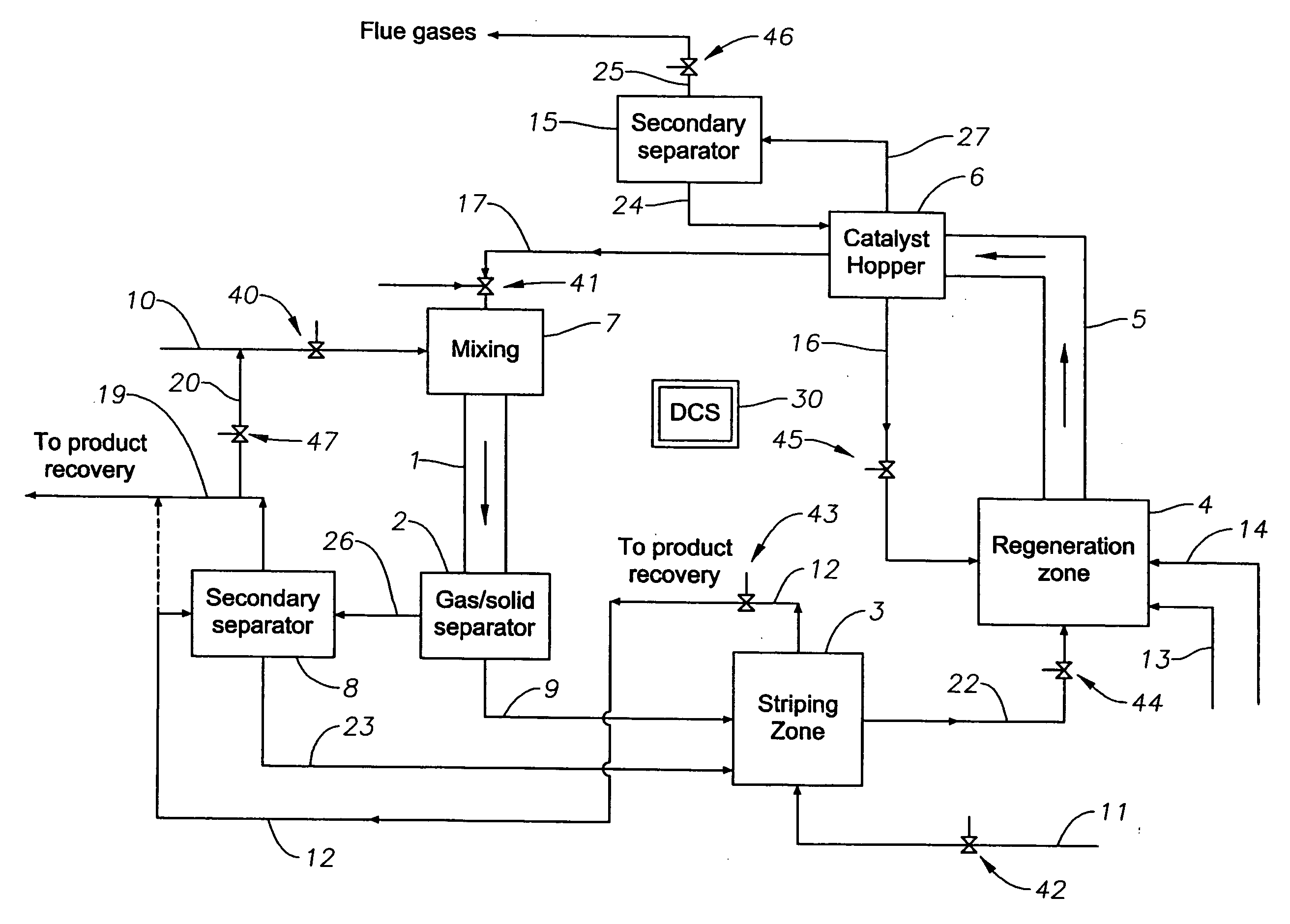
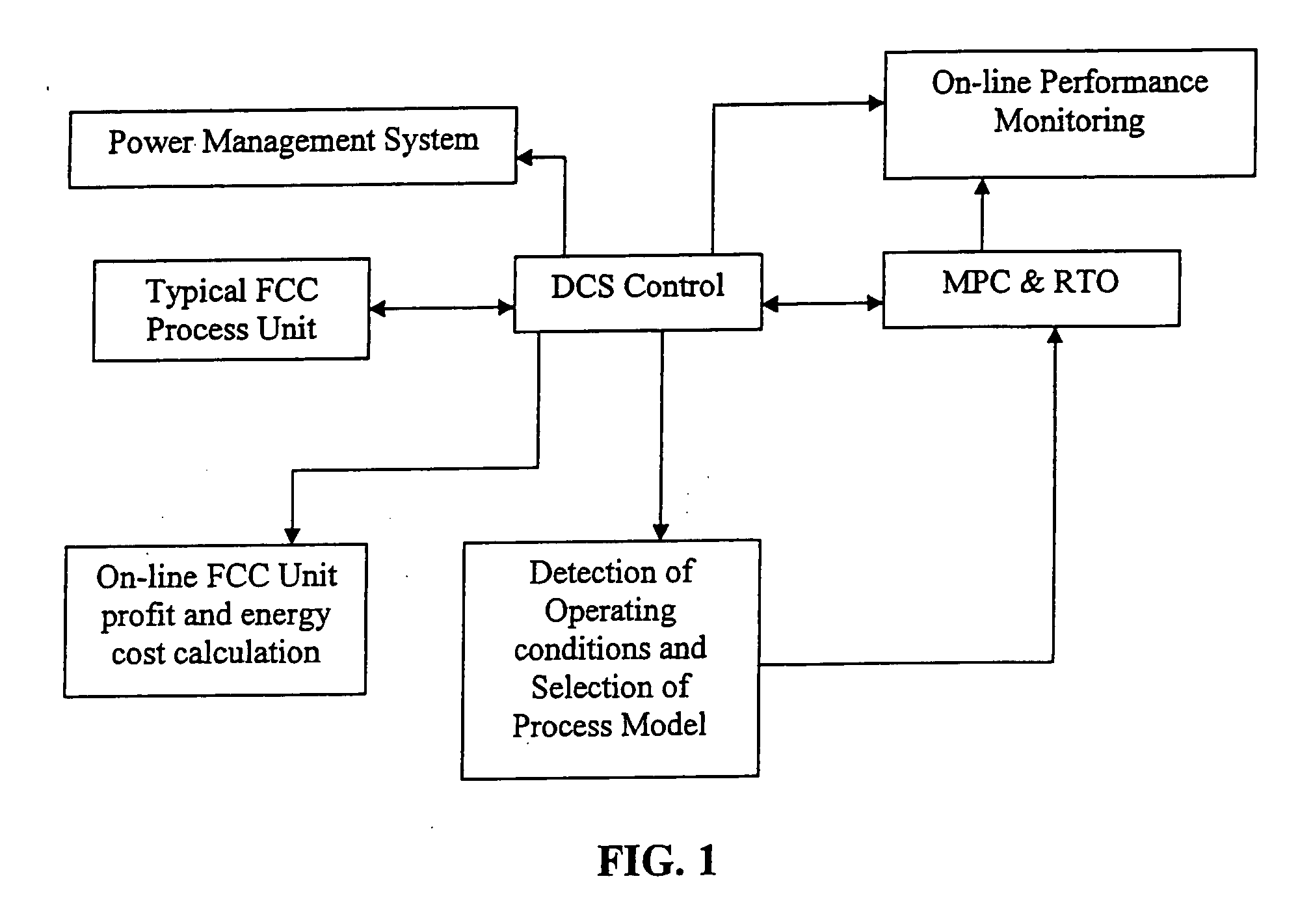
[0018]In one aspect, the invention relates to FCC processes for maximizing production of light olefins, particularly propylene, by utilizing a cracking catalyst comprising both large and medium pore, shape-selective zeolite components, and the use of advanced process control and optimization systems. The FCC feed can be catalytically cracked to produce a cracked material which comprises naphtha and propylene, and can include recovery and the subsequent recycle of at least a portion of the cracked material as feed, in which it is catalytically cracked under relatively severe operating conditions into products comprising additional propylene. In this manner, propylene production per unit of hydrocarbon feed can be maximized, by using the advanced process control.
[0019]Another objective of this invention is to provide an improved catalytic process for the fluid catalytic cracking of petroleum oil, which can produce light-fraction olefins with a high yield, while producing a diminished amount of dry gases such as gaseous hydrogen, methane, and ethane generated by the thermal cracking of the oil by appropriate process automation and control. In one aspect, this objection can be achieved through the use of a downer reactor or down-flow FCC reactor to reduce back mixing. Back mixing is the primary reason of overcracking which results in the formation of a large amount of dry gas. The reduction of back mixing reduces coke and dry gas formation resulting in increased production of gasoline and propylene.
[0020]In an attempt to mainly raise the yield of light-fraction olefins, fluid catalytic cracking of a petroleum oil is performed at a high temperature and at a short contact time by contacting the petroleum oil with a catalyst mixture. The catalyst mixture preferably includes a specific base cracking catalyst and an additive containing a shape-selective zeolite. The application of advanced control systems to maximize propylene production with minimum costs are also preferably utilized as part of the FCC process.
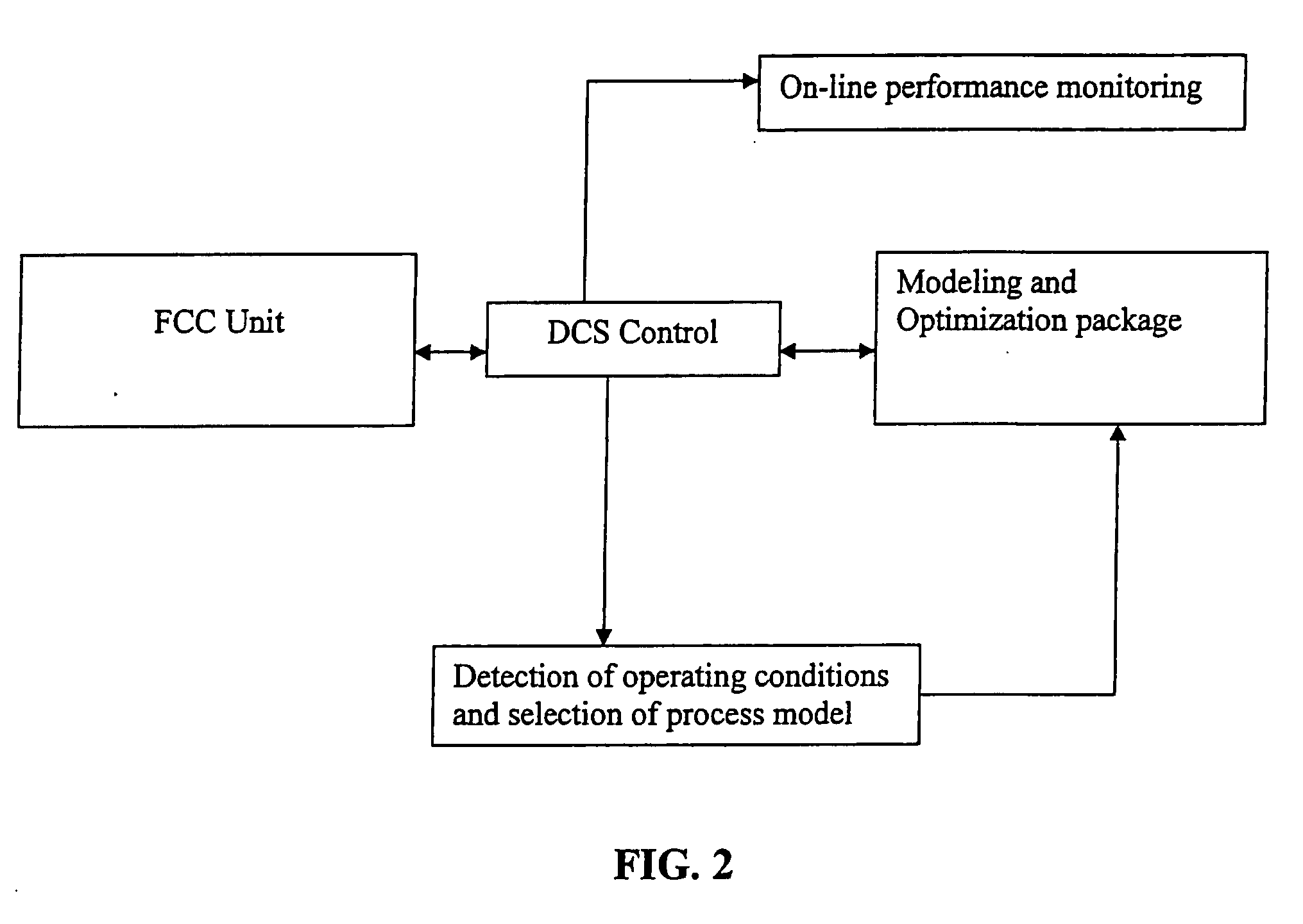
[0023]In particular, catalyst injections and other operating conditions can be remotely monitored and automatic adjustments can be made to the system outputs, thus reducing the reliance on human interactions such as monitoring and manual changes to the catalyst injection schedule and other process variables. A portion of unconverted oil can be recycled with feed.
[0024]Another objective of the proposed invention is to maximize the yield of light-fraction olefins by fluid catalytic cracking of a petroleum oil at a high temperature and at a short contact time, wherein the petroleum oil is contacted with a catalyst mixture that consists of a specific base cracking catalyst and an additive containing a shape-selective zeolite. Maximizing the yield of light-fraction olefin can also be obtained in accordance with one aspect of the invention by application of advanced control systems to maximize propylene production with minimum costs.

Problems solved by technology

The prior art systems are aimed at systems that focused on gasoline making, and therefore were not optimized for production of light olefins, such as for example, propylene.

Method used


Image

  • Advanced control of severe fluid catalytic cracking process for maximizing propylene production from petroleum feedstock
  • Advanced control of severe fluid catalytic cracking process for maximizing propylene production from petroleum feedstock
  • Advanced control of severe fluid catalytic cracking process for maximizing propylene production from petroleum feedstock

Examples


case b

results:

Conversion (in wt %):86.3% (Comparative example 2)Yield of (in wt %):Dry gas3.8Propylene11.3Butenes15.0Gasoline48.7LCO+13.7Coke2.7

[0106]Case C was conducted in accordance with the disclosure and teachings contained herein and include application of advance Process Control and Monitoring tools.

Case C results include:

Conversion (in wt %)97.6% (Example with APC)Yield of (in wt %):Dry gas4.2Propylene18.7Butenes22.95Gasoline41.65LCO+4.3Coke0.98

[0107]The benefits of using automation and monitoring tools, as set out in Case C include, but are not limited to, the following. As can be seen in Case A and Case B, the conversion rate varied from 86.3% to 95.6%, and the propylene yield ranged from 11.3 to 18.7, representing approximately an 11% variation in conversion rate and approximately a 65% variation in propylene yield by changing operating conditions, mainly catalyst to oil ratio and reactor temperature. This shows a high potential for improvements using on-line monitoring and adv...


PUM

PropertyMeasurementUnit
Temperatureaaaaaaaaaa
Timeaaaaaaaaaa

Abstract

With an aim to optimize propylene production, petroleum oil such as gas oil is catalytically cracked by contacting the oil with catalyst mixture consisting of a base cracking catalyst containing an stable Y-type zeolite and small amounts of rare-earth metal oxide, and an additive containing a shape-selective zeolite, in a down-flow type fluid catalytic cracking apparatus having a regeneration zone, a separation zone, and a stripping zone, wherein conversion of hydrocarbon occurs under relatively severe conditions. According to this fluid catalytic cracking process, the production of light-fraction olefins such as propylene is maximized by applying appropriate process control, monitoring, and optimizing systems. Process model and historical data to test a predictive system can provide early warning of potential performance degradation and equipment failure in the FCC unit.

Description

RELATED APPLICATIONS[0001]This application is related to and claims priority and benefit of U.S. Provisional Patent Application Ser. No. 60 / 857,300, filed Nov. 7, 2006, titled “Advanced Control of Severe Fluid Catalytic Cracking Process for Maximizing Propylene Production from Petroleum Feedstock,” which is incorporated herein by reference in its entirety.BACKGROUND OF THE INVENTION[0002]1. Field of the Invention[0003]This invention relates to a process for catalytic cracking of petroleum oil. More particularly, it relates to the application of appropriate control and monitoring conditions to a fluid catalytic cracking (“FCC”) process operating at relatively high severity conditions, which includes cracking of petroleum oil to obtain a maximum yield of a light olefin such as propylene, thereby maximizing propylene production per unit of hydrocarbon feed.[0004]2. Description of the Prior Art[0005]Although steam pyrolysis is widely practiced in process of cracking petroleum oil, this ...

Claims


Application Information

Patent Timeline
IPC IPC(8): C10G51/04
CPCB01J23/10B01J29/084B01J29/40B01J29/80C10G11/05C10G11/187C10G2400/20C10G2300/1033C10G2300/1044C10G2300/1059C10G2300/1074C10G2300/4006C10G2300/4081G05D21/02C07C4/06C10G11/04C10G11/18
Inventor KHAN, M. RASHIDTAHA, OTHMAN A.
Owner SAUDI ARABIAN OIL CO
Learn More