
Lighting device and projector

a technology of projector and light source, which is applied in the direction of lighting and heating equipment, point-like light sources, instruments, etc., can solve the problems of increasing power consumption and driving noise, unfavorable image display effect, and inability to easily recognize speckle patterns, etc., so as to achieve further effective reduction of speckle noise, and reduction of loss of light caused by reflection

Inactive Publication Date: 2008-05-29
COLUMBIA PEAK VENTURES LLC
View PDF2 Cites 20 Cited by
  • Summary
  • Abstract
  • Description
  • Claims
  • Application Information

AI Technical Summary

Benefits of technology

[0006]It is an advantage of some aspects of the invention no provide a lighting device capable of effectively reducing speckle noise by using a compact structure, and a projector including this lighting device.

Problems solved by technology

The speckle noise recognized during display of an image has undesirable effect on the image to be displayed, since the audience is dazzled by flickering light produced by the speckle noise.
In this case, a particular speckle pattern cannot be easily recognized by superposing a plurality of speckle patterns.
Additionally, since the relatively large-sized diffusing plate is rotated at high speed in the technology disclosed in JP-A-7-297111, power consumption and driving noise also increase.
It is thus difficult to use the technology of the high-speed rotation diffusing plate particularly for private use equipment without any improvement.
Particularly, while the speckle noise effectively decreases with increase in the number of light divisions, the size of the structure enlarges.
In this case, both the advantages of effective reduction of speckle noise and miniaturization of the structure are difficult to achieve at a time.
According to the technologies in the related art, therefore, reduction of speckle noise by using a compact structure is difficult.

Method used


Image

  • Lighting device and projector
  • Lighting device and projector
  • Lighting device and projector

Examples


first embodiment

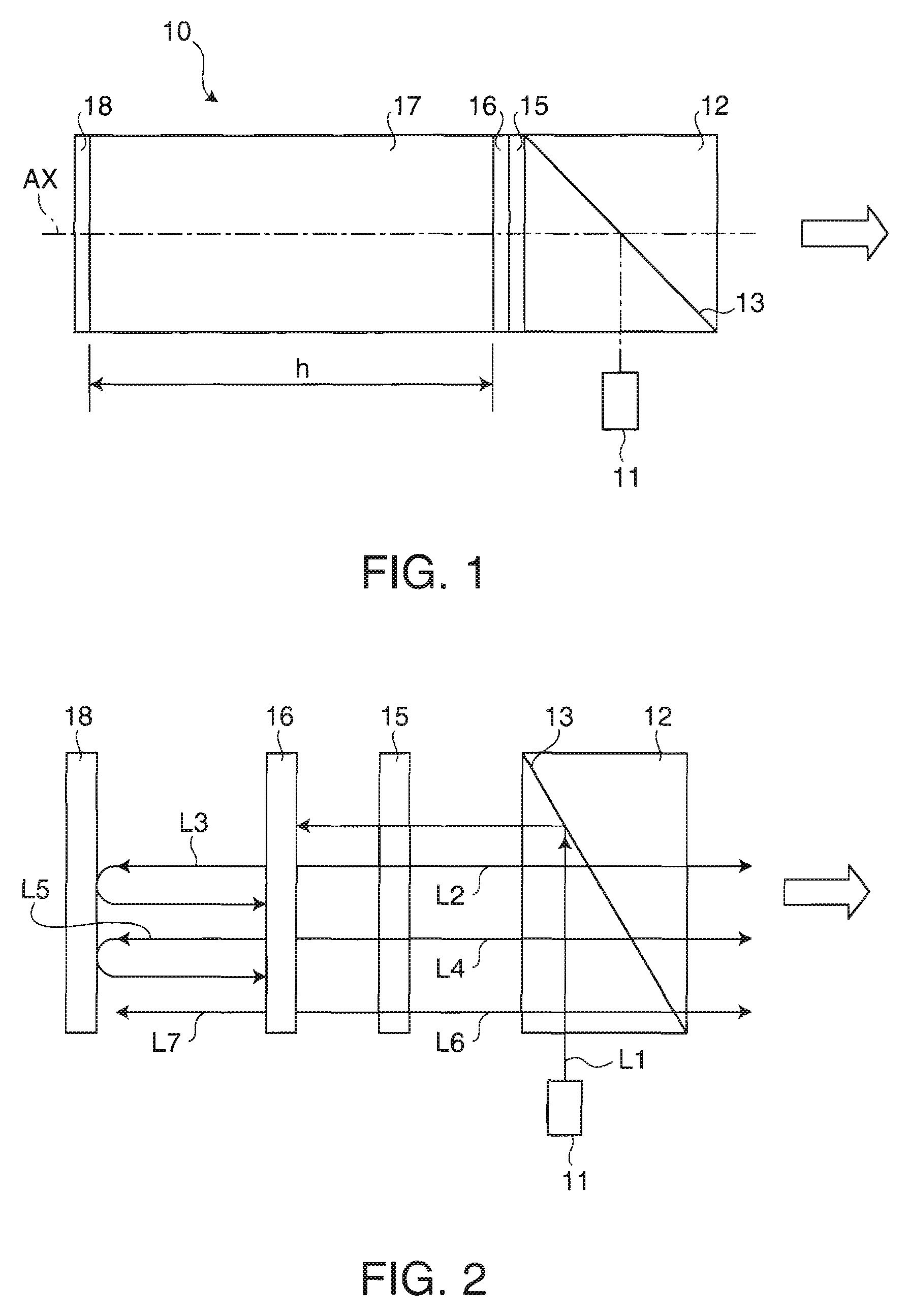
[0029]FIG. 1 schematically illustrates a structure of a lighting device 10 in a first embodiment according to the invention. The lighting device 10 emits light in a lighting direction shown by a white arrow in the figure. A light source unit 11 is disposed in a direction substantially orthogonal to the lighting direction. The light source unit 11 supplies laser beam as coherent light. The laser beam supplied from the light source unit 11 is s-polarized light, for example. The s-polarized light is a first polarized light having a first oscillation direction. Examples of lasers supplied from the light source unit 11 involve semiconductor laser, diode-pumped solid-state (DPSS) laser, solid laser, liquid laser, gas laser, and other lasers. A wavelength converting element which converts the wavelength of the laser light, such as a second-harmonic generation (SHG) element may be included in the light source unit 11.

[0030]A polarized beam splitter 12 is disposed at a position to which the ...

second embodiment

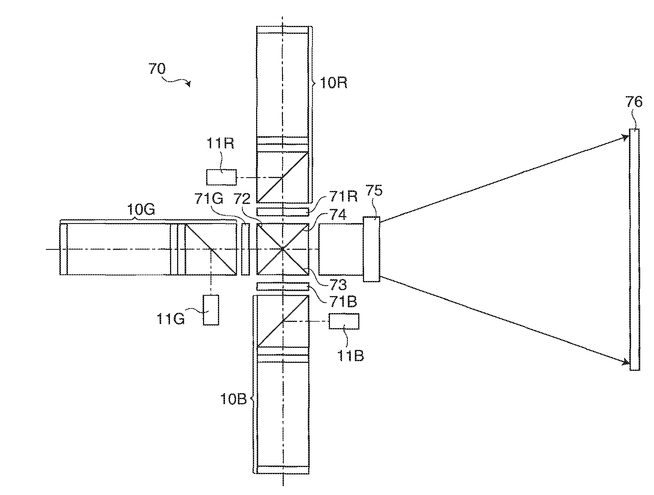
[0060]FIG. 9 schematically illustrates a structure of a projector 70 according to a second embodiment of the invention. The projector 70 is a front projection type projector which supplies light to a screen 76 to display an image to be observed produced by reflected light on the screen 76. The projector 70 includes a lighting device 10R for red color (R) light, a lighting device 10G for green color (G) light, and a lighting device 10B for blue color (B) light.

[0061]The lighting device 10R for R light has a light source unit 11B for R light. The light source unit 11R for R light is a light source unit which supplies laser beam of R light. The lighting device 10G for G light has a light source unit 11G for G light. The light source unit 11G for G light is a light source unit which supplies laser beam of G light. The lighting device 10B for B light has a light source unit 11B for B light. The light source unit 11B for B light is a light source unit which supplies laser beam of B light....


PUM


Abstract

A lighting device includes: a light source unit which supplies coherent light; a polarized light splitting unit which reflects first polarized light having first oscillation direction and transmits second polarized light having second oscillation direction substantially orthogonal to the first oscillation direction to split the first polarized light from the second polarized light; a reflection unit which reflects light advancing in a direction other than the lighting direction from the polarized light splitting unit; a partial reflection unit disposed between the polarized light splitting unit and the reflection unit to transmit a part of entering light and reflect the other part of the entering light; and a wavelength plate disposed between the polarized light splitting unit and the partial reflection unit no vary polarization condition of entering light. The partial reflection unit and the reflection unit produce optical path difference between light which passes through the partial reflection unit and the polarized light splitting unit to be released in the lighting direction and light which sequentially passes through the partial reflection unit, the reflection unit, the partial reflection unit, and the polarized light splitting unit to be released in the lighting direction.

Description

BACKGROUND[0001]1. Technical Field[0002]The present invention relates to a lighting device and a projector, and particularly to a technology of a lighting device which uses laser beams.[0003]2. Related Art[0004]When laser beams as coherent lights are applied to a diffusing surface, coherent patterns called speckle noise containing randomly distributed bright points and dark points appear in some cases. The speckle noise is caused by random coherences between diffused lights at respective points on the diffusing surface. The speckle noise recognized during display of an image has undesirable effect on the image to be displayed, since the audience is dazzled by flickering light produced by the speckle noise. Technologies for reducing the speckle noise have been proposed in JP-A-7-297111 and JP-A-5-196869, for example. According to the technology disclosed in JP-A-7-297111, speckle patterns are varied by rotating a diffusion plate provided on an optical path at high speed. In this case...

Claims


Application Information

Patent Timeline
IPC IPC(8): G03B21/28F21V19/04F21Y101/00
CPCG03B21/00G03B33/06H04N9/3167H04N9/3129G03B33/12G03B21/006
Inventor MATSUBARA, TAKAYUKI
Owner COLUMBIA PEAK VENTURES LLC
Learn More