
Integrated Sensor System Monitoring and Characterizing Lightning Events

a sensor system and integrated technology, applied in the field of electromagnetic sensor systems, can solve the problems of large integration of prior high sensitivity induction sensors, cumbersome system, and inability to monitor lightning events at the same time, and achieve the effect of reducing the number of sensors

Inactive Publication Date: 2008-05-29
QUASAR FEDERAL SYST
View PDF11 Cites 38 Cited by
  • Summary
  • Abstract
  • Description
  • Claims
  • Application Information

AI Technical Summary

Benefits of technology

[0019]In accordance with a particular aspect, this invention pertains to a compact integrated system for measurement of the electromagnetic signals produced by lighting. The system has the capability to determine the direction and distance to a lightning strike or event without input from sensors at other locations. Furthermore, the system can detect both conventional short-duration lightning events and also the less common, but more destructive, continuing current lightning. Such a system has use in protecting life and personal property. Its compact nature makes it possible to install the system in small aircraft and boats, or to hand-carry it to an area of interest, such as a forested area that might be prone to fires.
[0020]The invention is based on both electric (E) and magnetic (B) field sensors that are integrated into a compact package. The basic form of the system combines one E-field and two B-field sensors arranged in orthogonal directions. To accurately determine the direction from the sensor system to the lightning event, the system is aligned with the E-field detection axis to the vertical and the B-field horizontal in North-South and East-West directions by reference to external instruments, or preferably orientation and tilt sensors are integrated into the sensor to allow the data that is collected to be projected into these cardinal directions. Alternatively, the lightning detection sensor can incorporate 3-axis B-field and / or 3-axis E-field sensors. From the well defined polarization of the electromagnetic signal produced by lightning, the 3-axis sensor outputs are used to determine the components of the B-field in the horizontal plane and the component of the E-field in the vertical direction. The respective sensors are about one hundred times smaller than conventional E and B sensors, allowing a very compact overall unit. Their ultra-high sensitivity makes it possible to detect lightning discharges from very long distances of up to 1000 km. The simultaneous measurement of the electric and magnetic fields allows the direction to the lightning stroke to be determined, while the time between the initial direct signal and signals that have bounced off the ionosphere allow the distance to the stroke to be determined. The entire sensor system is preferably less than 30 cm in any dimension, and, more preferably, less than 20 cm. Preferably the E-field sensor is a solid-state device with no moving parts and mounted onto the end of a B-field sensor.

Problems solved by technology

Depending on the accuracy required, such an installation can take a significant time to complete and requires an area in the order of 10 m2 to operate.
Prior high sensitivity induction sensors have been too large to integrate together.
While one cylindrical object of length even up to 2 m is relatively easy to handle and transport, a system comprised of two or three such sensors at right angles to each other, if even contemplated, would be very cumbersome.
Simply stated, prior induction sensors and arrangements that involve them are quite large and sub-optimal, while being inefficient to set-up and operate.
The time consuming set-up and lack of compactness in prior proposals has essentially limited the use of collected E-field and B-field information to geophysical applications, such as magnetotellurics and the measurement of lightning, wherein the sensors can be positioned over a relatively wide area.
This technique cannot be applied to systems on the ground.
It is not always convenient to maintain a long distance data link and further, in most parts of the world, a large installed array, such as the NLDN, does not exist.

Method used


Image

  • Integrated Sensor System Monitoring and Characterizing Lightning Events
  • Integrated Sensor System Monitoring and Characterizing Lightning Events
  • Integrated Sensor System Monitoring and Characterizing Lightning Events

Examples


Embodiment Construction

[0033]The present invention provides advances in connection with establishing a compact sensor system that can measure multiple vector components of both electric and magnetic fields at very high sensitivity. By a “compact” sensing system it is meant that the region over which a particular field is measured is small relative to the spatial variations in the field that are of interest, and / or is sufficiently compact that a system that measures multiple components of the field is of a convenient size. As will become fully evident below, the compact nature and arrangement of the various sensors allows the sensors to intersect at a common center, while enabling minimum lateral offsets between the sensors.

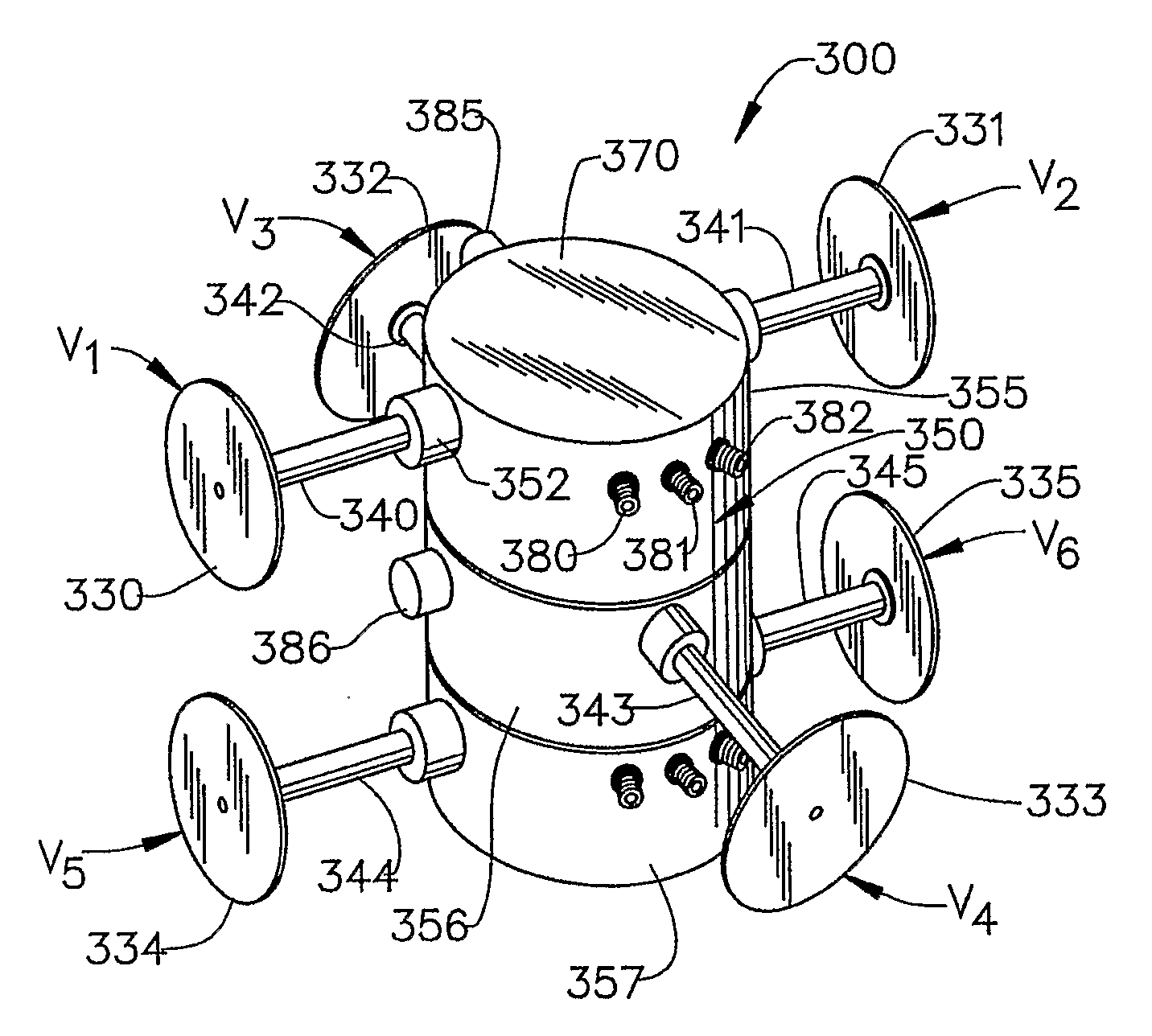
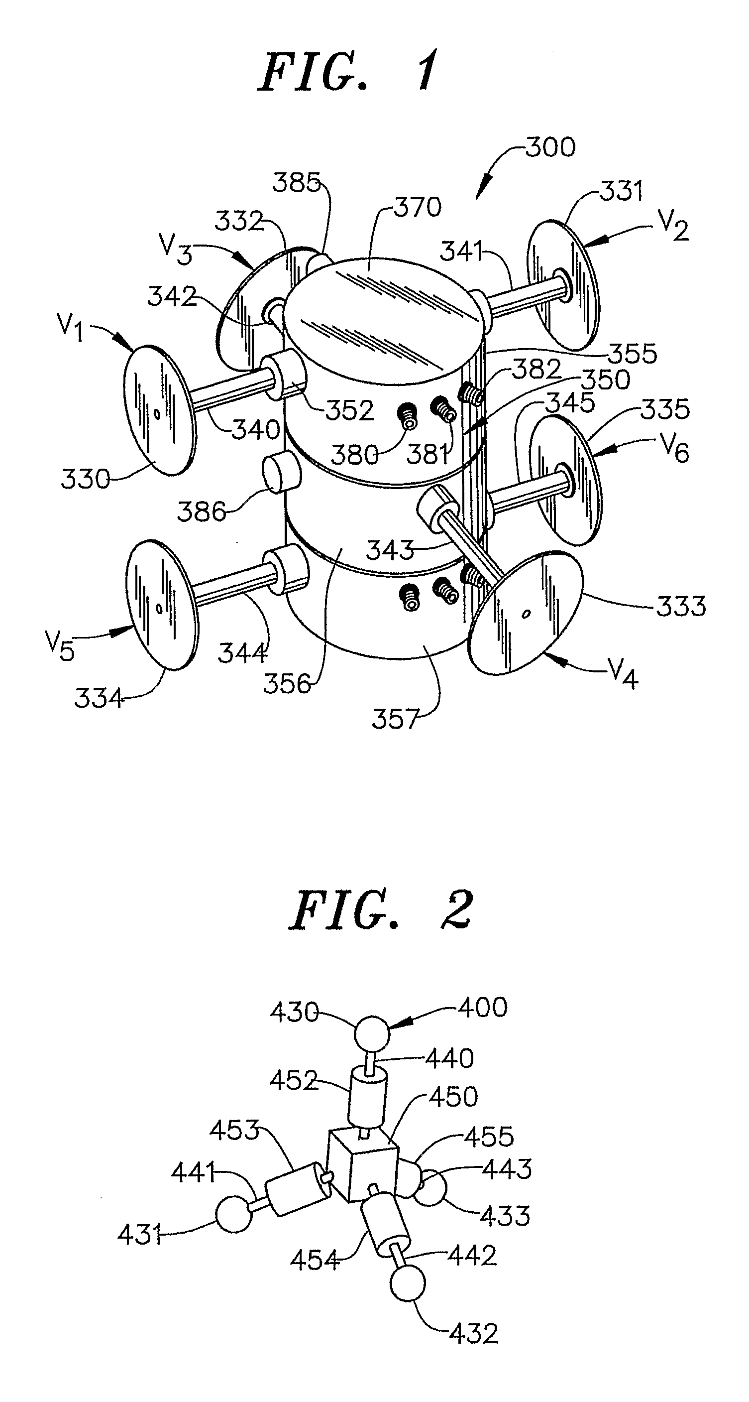
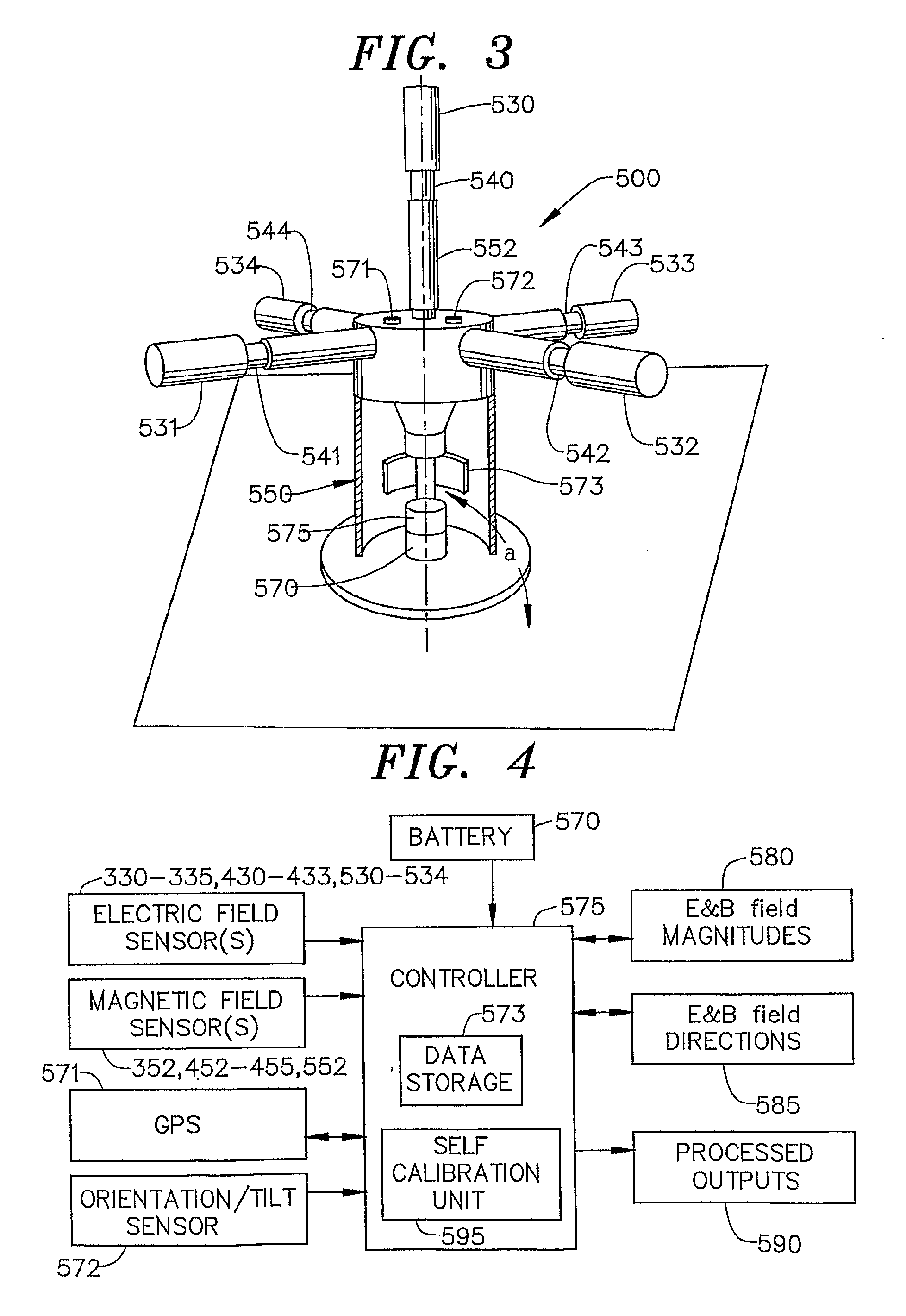
[0034]An example of a multi-axis, combined E-field and B-field sensor system 300 built according to a preferred embodiment of the invention is shown in FIG. 1. In this system, three orthogonal axes of an electric field are measured with various capacitive sensors 330-335 arranged as pai...


PUM


Abstract

A compact sensor system integrates electric and magnetic field sensors to accurately measure, with a high level of sensitivity, electric and magnetic fields. The sensor system is self-contained so as to include a built-in power source, as well as data storage and / or transmission capability. The integrated sensor system also preferably includes a global positioning system (GPS) to provide timing and position information, a sensor unit that can determine the orientation and tilt of the sensor system, and self-calibrating structure which produces local electric and / or magnetic fields used to calibrate the sensor system following deployment. The system measures the electromagnetic signals produced by lightning and more has the capability to determine the direction and distance to a lightning event without input from sensors at other locations. Furthermore, the system can detect both conventional short-duration lightning events and also the less common, but more destructive, continuing current lightning.

Description

CROSS-REFERENCE TO RELATED APPLICATION[0001]The present application is a continuation-in-part of U.S. application Ser. No. 10 / 959,480 entitled “Integrated Sensor System for measuring electrical and / or magnetic field vector components” filed on Oct. 7, 2004 which claims the benefit of U.S. Provisional Patent Application Ser. No. 60 / 509,423 entitled “Integrated Electric and Magnetic Field Sensor” filed Oct. 7, 2003 and also claims the benefit of U.S. Provisional Patent Application Ser. No. 60 / 645,729 entitled “Integrated EM Sensor for Lightning Monitoring and Characterization” filed Jan. 24, 2005.STATEMENT REGARDING FEDERALLY SPONSORED RESEARCH OR DEVELOPMENT[0002]The U.S. Government has a paid-up license in this invention and the right in limited circumstances to require the patent owner to license others on reasonable terms as provided for by the terms of DARPABACKGROUND OF THE INVENTION[0003]1. Field of the Invention[0004]The present invention pertains to systems for measuring elec...

Claims


Application Information

Patent Timeline
Patent Type & Authority Applications(United States)
IPC IPC(8): G01W1/00
CPCG01R29/0842
Inventor ZHANG, YONGMINGHIBBS, ANDREW D.MATTHEWS, ROBERTJABSON, DAVID MATTHEW
Owner QUASAR FEDERAL SYST
Learn More