
Double chamber variable condiment dispenser bottle

a condiment dispenser and variable technology, applied in the field of condiment dispensers, can solve the problems of large number of separate condiment containers becoming unwieldy and time-consuming to use, cap dropping, contaminated or completely lost, time-consuming to determine which cap, etc., to achieve convenient stacking of bottles, reduce leakage, and facilitate the effect of convenient us

Inactive Publication Date: 2008-05-29
PIKOWSKI DAN
View PDF4 Cites 19 Cited by
  • Summary
  • Abstract
  • Description
  • Claims
  • Application Information

AI Technical Summary

Benefits of technology

[0015]An object of this invention is to provide a convenient and quick way to dispense two liquid condiments at the same time. A further object of this invention, during the dispensing of two liquid condiments at the same time, is the ability to vary the nozzle openings to account for different viscosities of the condiments. This allows one to adjust the proportion of the flow of the condiments as desired.
[0016]This invention is a condiment bottle made from a squeezable plastic material that has the ability to return to its original shape after squeezing. It has two chambers that allow for two compatible condiments, such as mustard and ketchup, to be dispensed together. The head of the bottle contains a nozzle for each chamber. A further object of this invention is the ability to vary the size of the opening of each nozzle by turning the appropriate valve for each nozzle. One can make these adjustments during dispensing for a more precise flow of condiments of different viscosities. Either condiment can be dispensed independently of the other, by rotating the valve for the unwanted condiment to the closed position. The bottle can be made from a transparent or translucent plastic material to help identify the condiments of each chamber.
[0017]A further object of this invention is the shape of each nozzle opening. Each nozzle opening is shaped into a narrow rectangular slot or aperture that discourages leakage of each condiment chamber when the bottle is inverted. This feature prevents the inadvertent release of the condiments until the bottle is squeezed. The valves maintain an airtight fit with the valve housing to prevent leakage of the condiments except through the narrow rectangular slots or apertures of each nozzle. Further, when the valves are rotated to the closed position, the airtight fit prevents the drying out of the condiments, both in the valves and in the chambers. This eliminates the need for separate caps on each nozzle. A clear plastic cover is fitted over the head of the bottle to assist in providing an airtight seal and make convenient stacking of the bottles possible. Both the bottom of the dual chambered bottles and the plastic covers are flat for stable stacking of several bottles. Further, the condiment bottles can be stored in an inverted position, thereby retaining the condiments at their respective nozzles for immediate use.

Problems solved by technology

In large food service settings, such as those found in schools, hospitals, and stadiums, for example, a large number of separate condiment containers can become unwieldy and time consuming to use.
Because of their relatively small size, these caps can be easily dropped and contaminated or lost completely.
Often it can be time consuming to determine which cap goes on which nozzle.
These problems are amplified in large food service settings where time is further wasted in handling a large number of conventional condiment dispensers.
The nozzles are the same size, therefore not allowing for contents of different viscosities to flow equally or in proportions desired by the user.
If one compartment contains oil, and the other vinegar, the vinegar will flow more freely, releasing much more vinegar than oil in unwanted proportions.
The inability to control the size of the nozzle opening presents difficulty when dispensing contents with dissimilar viscosities.
This dispenser would be inapplicable for liquids.
This container does not have a means to adjust the size of the nozzles for each chamber.
This bottle could not function as a dispenser for liquid condiments.
This would not allow contents of dissimilar viscosities to dispense equally or in desired proportions.
But that is seldom the case.

Method used


Image

  • Double chamber variable condiment dispenser bottle
  • Double chamber variable condiment dispenser bottle
  • Double chamber variable condiment dispenser bottle

Examples


Embodiment Construction

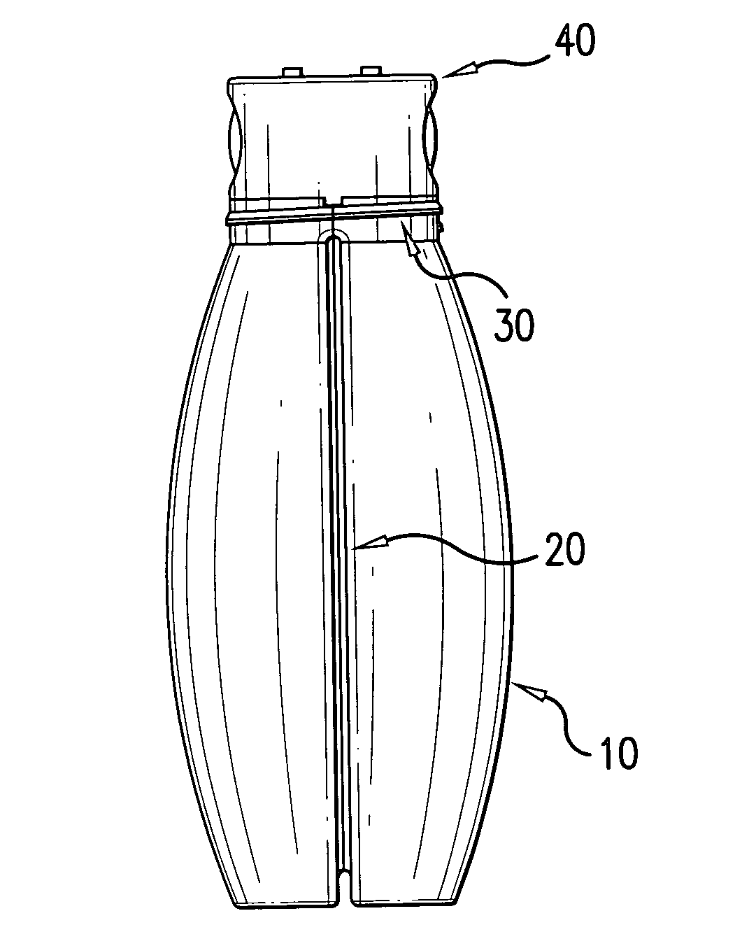
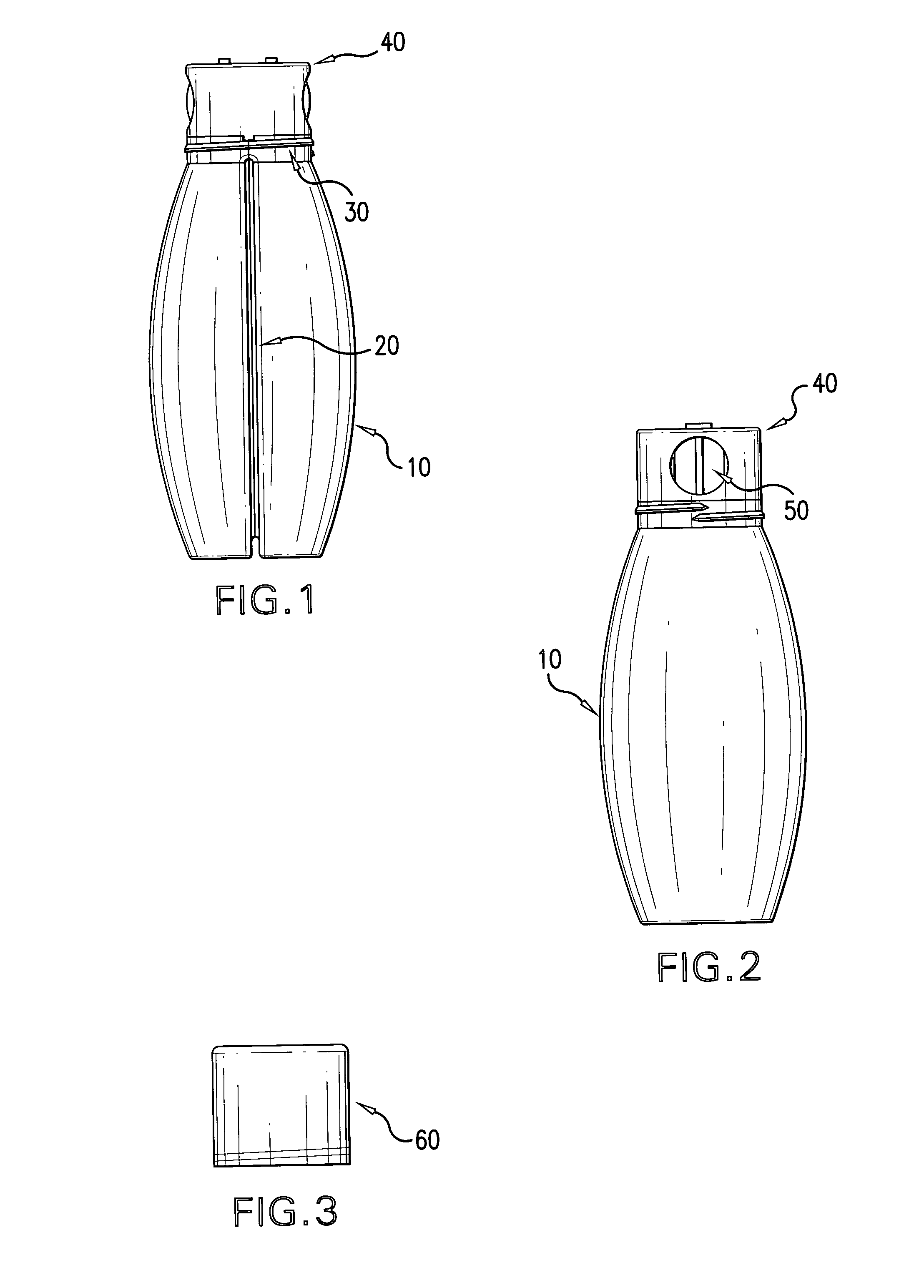
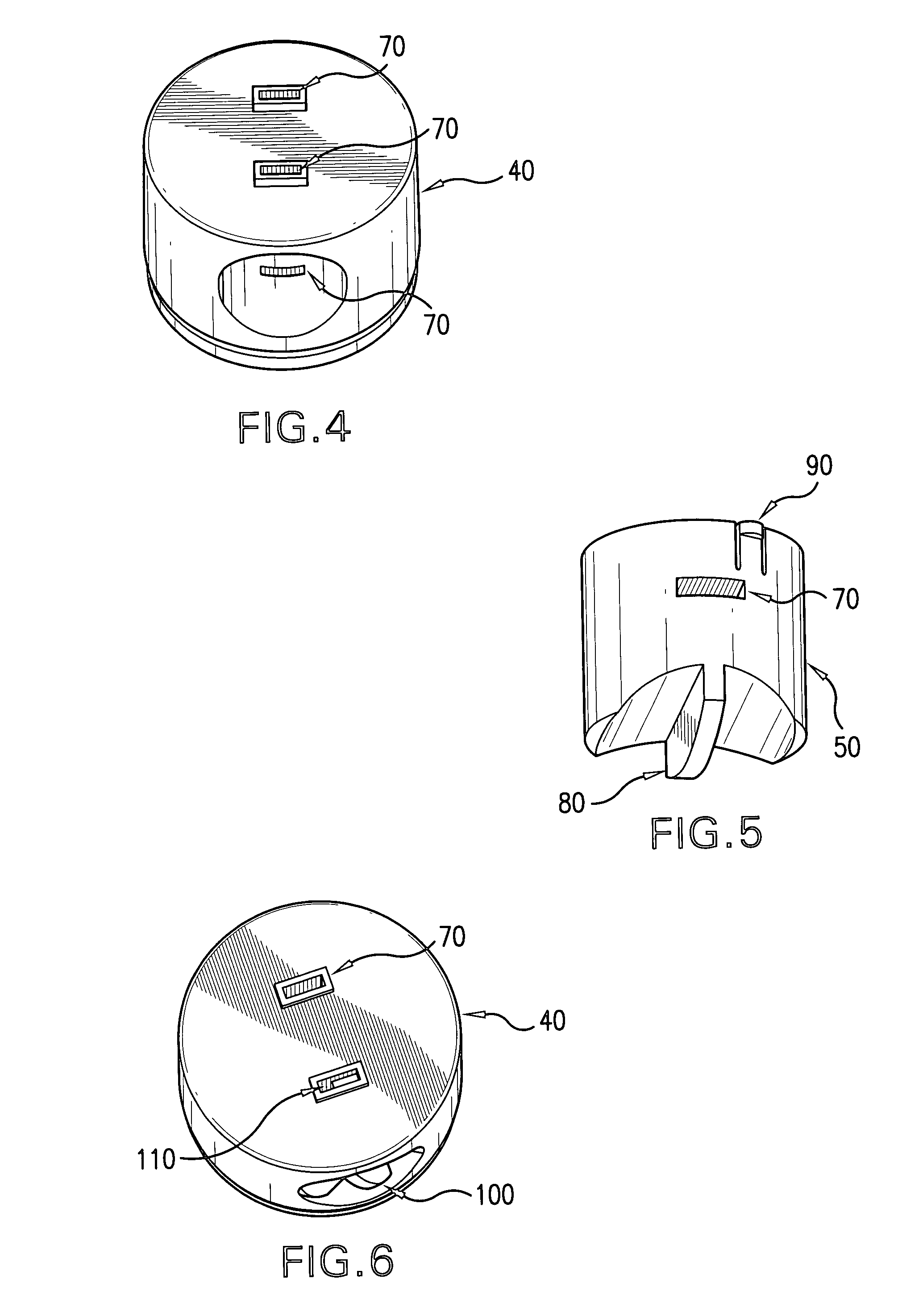
[0024]The current invention is a dual chambered condiment bottle 10 represented in FIG. 1. FIG. 2 is a ninety degree rotation about the vertical axis of the condiment bottle 10. As seen in FIG. 1, the condiment bottle 10 is divided into two sections by chamber divider 20. Condiment bottle 10 can be molded from polyethylene or polypropylene, but not limited to those materials alone. Any plastic or other material can be used provided that the material used has the property of being able to return to its original shape after being squeezed to force ejection of the desired amount of condiment(s). A threaded portion 30 is molded at the top of the condiment bottle 10 to engage the corresponding threaded portion molded in transparent cap 60 represented inFIG. 3. The bottom of condiment bottle 10 and the top of the transparent cap 60 are both flat and parallel to each other. This gives the condiment bottle 10 the additional convenience of allowing the stacking of other condiment bottles 10 ...


PUM


Abstract

The present invention discloses a dual chamber condiment bottle utilizing a rotatable valve above each chamber to adjust the amount of condiment released when squeezing the bottle. Each rotatable valve has a finger tab to adjust the amount of condiment released. Because condiments are often composed of different viscosities, such as mustard and ketchup, or oil and vinegar for salads, it is advantageous to have the adjustments for each chamber to release the desired ratio of the condiments when simultaneously dispensing them.

Description

BACKGROUND OF THE INVENTION[0001]1. Field of the Invention[0002]This invention generally pertains to liquid condiment dispensers. Specifically, this invention describes a dual chamber condiment bottle with a dispensing nozzle provided for each chamber that provides for variable dispensing of the contents of each chamber as the bottle is squeezed. The amount of each chamber's contents to be dispensed can be adjusted during the dispensing process. This feature allows fluids of different viscosities to have adjustable dispense rates suitable to the user.[0003]2. Description of the Prior Arts[0004]It is very common to store individual condiments in separate containers that also serve as dispensing containers when they are squeezed. Several different condiments are often used at one time, requiring picking up and squeezing a number of separate containers. In large food service settings, such as those found in schools, hospitals, and stadiums, for example, a large number of separate condi...

Claims


Application Information

Patent Timeline
Patent Type & Authority Applications(United States)
IPC IPC(8): B67D5/56B67D5/06B67D7/06B67D7/74
CPCA47G19/183A47G2019/122B65D47/30B65D1/32B65D1/04
Inventor PIKOWSKI, DAN
Owner PIKOWSKI DAN
Learn More