Rotating hinge with an elevating structure

a technology of rotating hinges and hinges, which is applied in the direction of wing accessories, instruments, portable computers, etc., can solve the problems of affecting the harmonic appearance of electronic devices, limiting the positioning effect and touch feel of positioning, and the screen may rub easily on the keyboard, so as to improve the stability of the display, reduce the overall volume of electronic devices, and improve the harmonic appearan

Inactive Publication Date: 2008-05-29
SINHER TECH INC
View PDF10 Cites 6 Cited by
  • Summary
  • Abstract
  • Description
  • Claims
  • Application Information

AI Technical Summary

Benefits of technology

[0006]The primary objective of the present invention is to provide a rotating hinge with an elevating structure, particularly a rotating hinge applicable to a display of an electronic device. Besides the display can be rotated with respect to the main body of the electronic device, the screen of the display can be driven to elevate or descend with respect to the main body during the rotating process to prevent the display from touching a keyboard, such that the display can be installed at a lower position to reduce the overall volume of the electronic device and give a better and more harmonic appearance to the electronic device.
[0007]Another objective of the present invention is to provide a touch feel for the positioning when the display is turned to a predetermined position, so as to resist vibrations of the display and greatly improve the stability of the display.
[0008]To achieve the foregoing objectives, a preferred embodiment of the present invention includes a fixed base and a rotating support base that can be rotated with respect to each other. An upper end of the fixed base is fixed to a guide plate, and the guide plate has a through hole for passing a wire, two or more external positioning grooves corresponding to internal positioning grooves, and these positioning grooves are designed according to the required positioning angle such as 0 degree and 180 degrees when the hinge is rotated, and the two external positioning grooves are disposed equidistantly with 180 degrees apart at the external circumference of the guide plate, and the two internal positioning grooves are disposed equidistantly at the internal circumference of the through hole. The number and angle of the internal positioning grooves correspond to those of the internal positioning grooves and disposed alternatively with each other. A lower end of the rotating support base connects and presses the guide plate and a limit plate linked to the rotating support base. The limit plate includes a set of internal positioning protrusion and external positioning protrusion disposed at the positions corresponding to the internal and external positioning grooves of the guide plate. When the rotating support base and the fixed base are rotated, the positioning grooves and positioning protrusions drive the position of the rotating support base to elevate. After the rotating support base rises, there are four or more points of the positioning protrusions situated at the internal and external circumferences of the guide plate, such that a four-point contact can be maintained to prevent and resist vibrations after the rotating support base rises. After the rotating support base is turned to a predetermined position, the positioning grooves and positioning protrusions match with each other, and the rotating support base is descended to a fixed position to enhance the touch feel and the stability after the front side and backside of the screen are positioned.

Problems solved by technology

As conventional rotating hinges do not come with a screen elevating structure, the screen may rub a keyboard easily if the screen is rotated and the height is insufficient or the screen is titled.
Therefore, it is necessary to elevate the screen, but such arrangement will adversely affect the harmonic appearance of the electronic device.
However, a poor design of the corresponding protruding edges and grooves of the foregoing rotating structure may affect the engagement of the protruding edge with the groove and limit the positioning effect and the touch feel of the positioning.
In addition, such device obviously does not come with the function of limiting the rotating path of the display, so that a signal line of the display connected to the main body cannot be twisted too much, and the display must be turned less than 360 degrees with respect to the rotating path of the main body.
Since the rotating path of the foregoing rotating structure is not limited, the signal line may be twisted and tangled and the electronic device may even be damaged easily.

Method used


Image

  • Rotating hinge with an elevating structure
  • Rotating hinge with an elevating structure
  • Rotating hinge with an elevating structure

Examples


Embodiment Construction

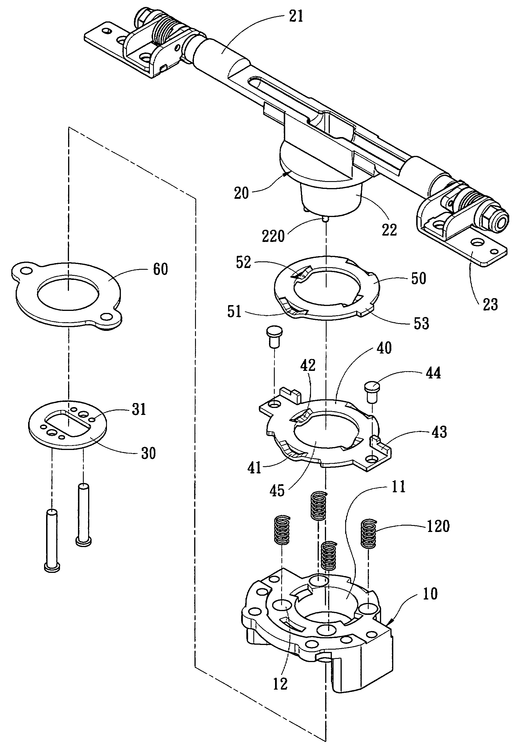
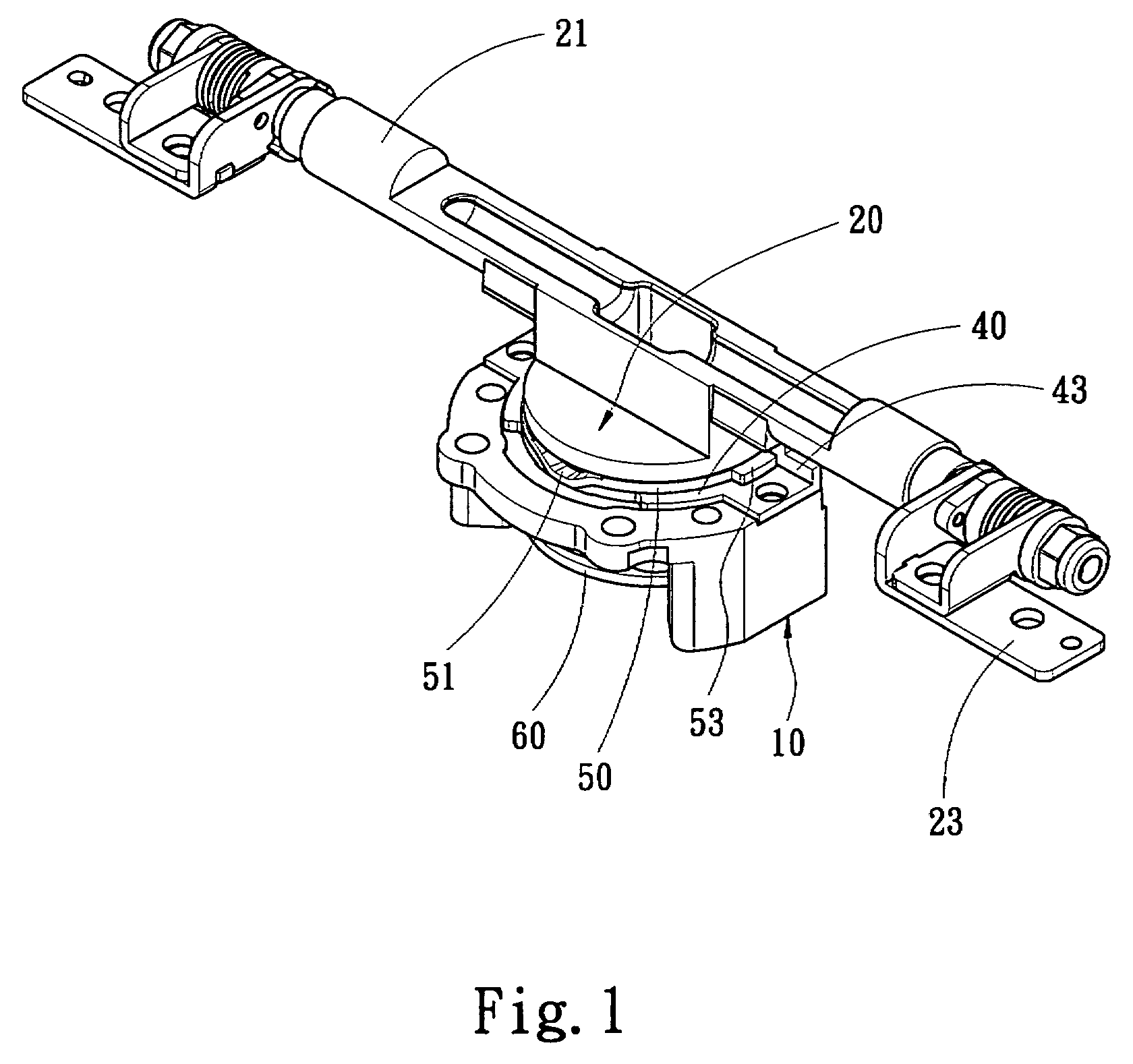
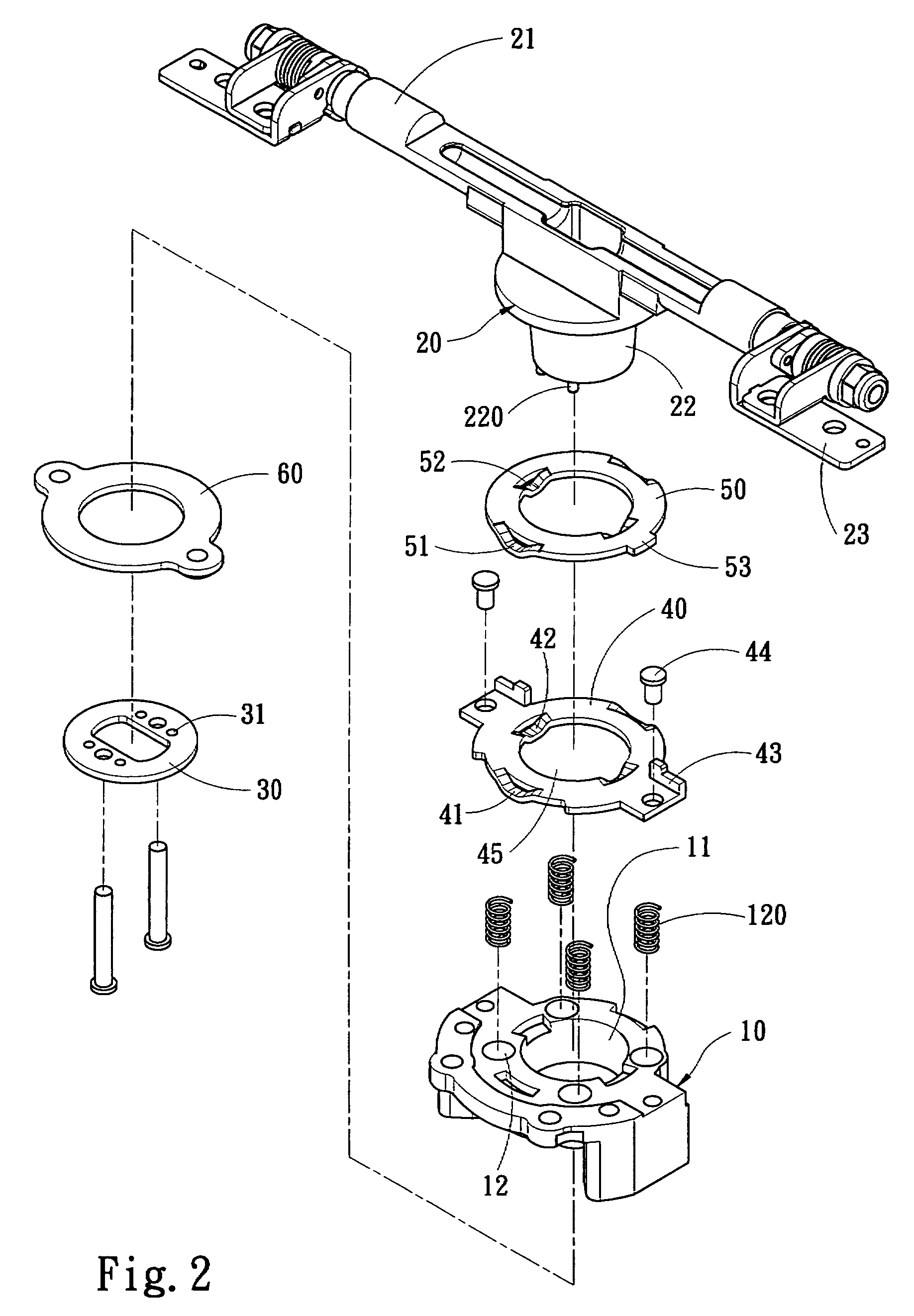
[0016]Referring to FIG. 1 for a preferred embodiment of the present invention, a rotating hinge is connected to a display 1 and a main body 2 (as shown in FIG. 6) of an electronic device A, and the display 1 can be spread open and rotated with respect to the main body 2. The rotating hinge with an elevating structure of the invention comprises a fixed base 10, a rotating support base 20, a guide plate 40 and a limit plate 50.

[0017]Referring to FIGS. 2 and 3, the rotating support base 20 is installed at the top of the fixed base 10 and includes an axle rod 21 installed on the display 1, a driving portion 22 linked with the axle rod 21 and two fixing members 23 disposed on both ends of the axle rod 21 for mounting the display 1, such that the display 1 can use the axle rod 21 as the axis to spread open the display 1 with respect to the main body 2. The rotating support base 20 further includes a rotating path with respect to the fixed base 10, so that the display 1 can be rotated with...


PUM


Abstract

A rotating hinge capable of driving a screen to ascend or descend includes a fixed base and a rotating support base. The fixed base has a guide plate with external positioning grooves corresponding to internal positioning grooves for pressing the guide plate, a limit plate linked to the rotating support base and corresponding to the internal and external positioning grooves, and internal positioning protrusion and external positioning protrusion. When the rotating support base is rotating, the positioning grooves and positioning protrusions rise. After the rotating support base rises, a four-point contact can be maintained stably to prevent and resist vibrations. When the rotating support base is rotated to a predetermined position, the positioning grooves and positioning protrusions will match with each other, and the rotating support base will be descended to a position to improve the touch feel and stability of driving a screen to ascend or descend.

Description

FIELD OF THE INVENTION[0001]The present invention relates to a rotating hinge with an elevating structure, and more particularly to a rotating hinge capable of elevating a screen to a fixed position and producing touch feel when the screen is descended.BACKGROUND OF THE INVENTION[0002]In general, a 3C electronic device such as a notebook computer, a personal digital assistant (PDA) a digital camera and a mobile phone, a display and a main body of the electronic device are pivotally connected by a hinge, so that the display can be spread open when the electronic device is in use, or the display can be can be folded onto the main body to reduce the volume for storage and carrying when the electronic device is not in use.[0003]As conventional rotating hinges do not come with a screen elevating structure, the screen may rub a keyboard easily if the screen is rotated and the height is insufficient or the screen is titled. Therefore, it is necessary to elevate the screen, but such arrange...

Claims


Application Information

Patent Timeline
Patent Type & Authority Applications(United States)
IPC IPC(8): E05D7/04
CPCE05D3/10E05Y2900/606G06F1/162Y10T16/5323G06F1/1681G06F1/1683H04M1/0212G06F1/1679
Inventor SU, DING-HONE
Owner SINHER TECH INC
Why Eureka
Try Eureka