
Vehicle

a technology for vehicles and vehicles, applied in the field of vehicles, can solve the problems of disabling sufficient absorption of energy, affecting the safety of pedestrians/occupants, so as to prevent overriding collisions and stabilize energy absorption

Inactive Publication Date: 2008-05-22
HITACHI LTD
View PDF1 Cites 8 Cited by
  • Summary
  • Abstract
  • Description
  • Claims
  • Application Information

AI Technical Summary

Benefits of technology

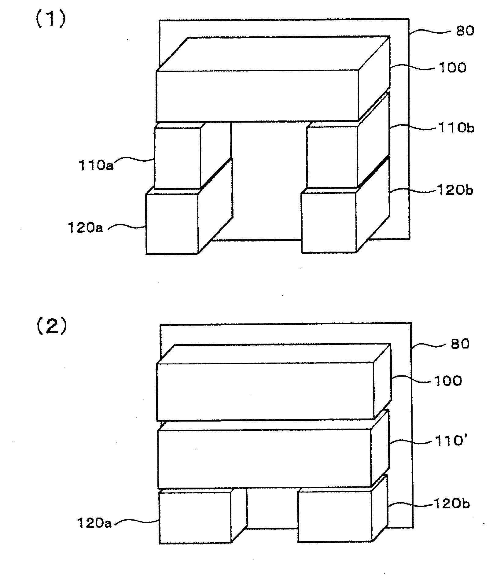
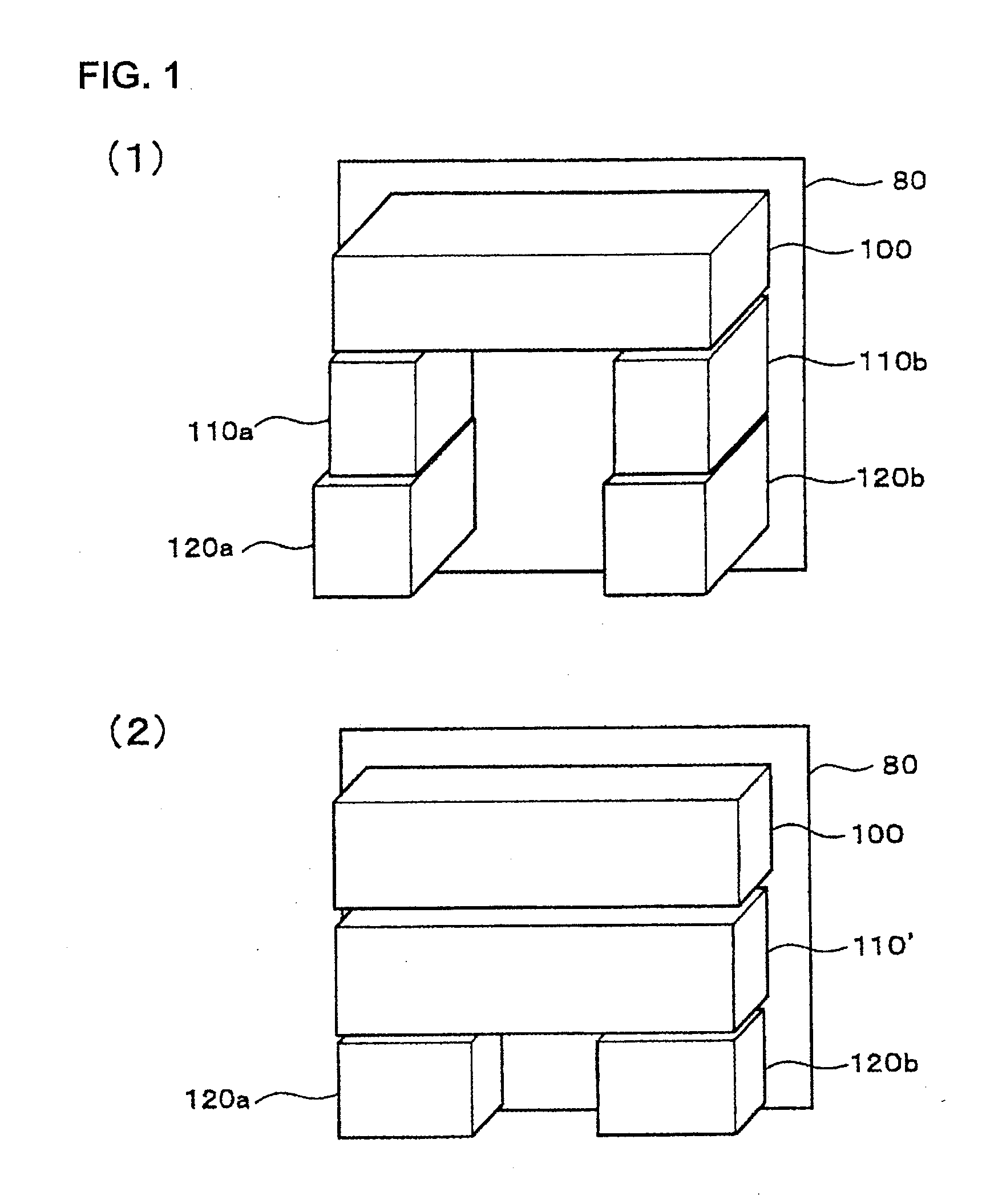
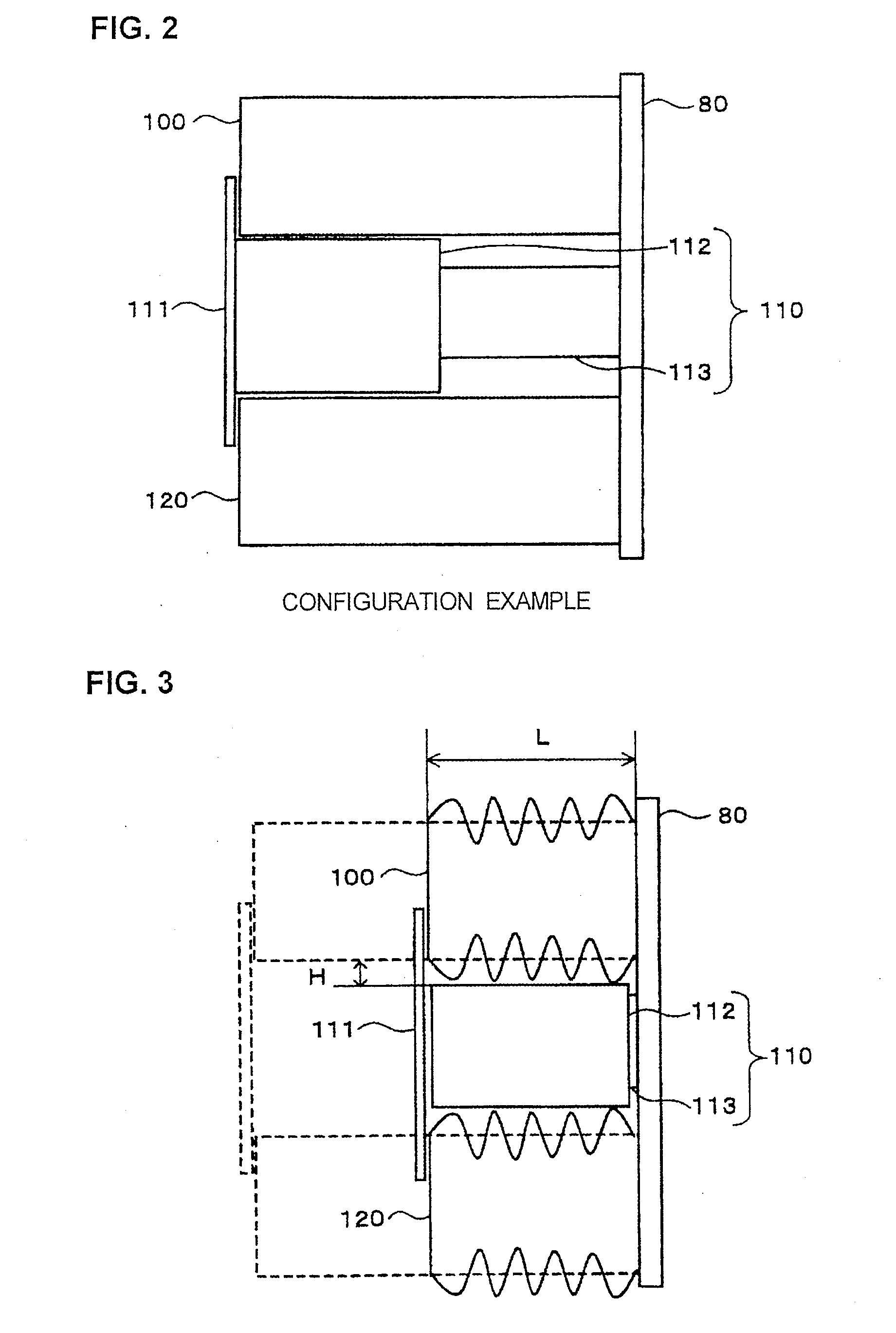
[0012]Also, a run-on preventing means that extends in the travel direction outside the end of the lower-stage shock absorbing means to provide a level difference is provided in a boundary part between the middle-stage shock absorbing means and the lower-stage shock absorbing means. Thereby, an overriding collision can be prevented.
[0013]Further, spaces wider than crush wrinkles of the upper and lower-stage shock absorbing means are secured between the middle-stage shock absorbing means and the upper-stage shock absorbing means and between the middle-stage shock absorbing means and the lower-stage shock absorbing means, and the buffer means having a length not longer than the crush remaining amount of the upper and lower-stage shock absorbing means is provided. Thereby, stable energy absorption can be realized.
[0014]According to the present invention, there can be provided a vehicle equipped with the shock absorbing structure that can absorb collision energy stably under all collision conditions to ensure the safety of crew members and passengers.

Problems solved by technology

For the transportation equipment typified by a railroad vehicle, a road vehicle, and the like, an unexpected collision may occur during running.
A problem with the above-described related art is that although a sufficient effect can be achieved against the collision at a position at which the energy absorbing block is arranged, collision energy cannot be absorbed stably under other collision conditions.
In this case, vehicles having shock absorbing structures of a different construction collide with each other, so that an offset collision in which the collision positions of energy absorbing blocks shift from each other occurs.
In the offset collision, a load is applied unbalancedly to the energy absorbing block, so that the energy absorbing block is curved while being not crushed sufficiently in the travel direction, disabling sufficient absorption of energy.
However, in the case where the plurality of energy absorbing blocks are crushed in association, there occur phenomena that a shock force at the time of collision is too strong, so that the crew members and passengers are injured, and that the survival zone, not the energy absorbing block, is crushed first.

Method used


Image

  • Vehicle
  • Vehicle
  • Vehicle

Examples


Embodiment Construction

[0023]One embodiment of the present invention will now be described with reference to the accompanying drawings. First, a general railroad vehicle body structure and shock absorbing structure are explained with reference to FIGS. 5 to 8.

[0024]FIG. 5 is a perspective view showing a configuration example of the general railroad vehicle body structure. In FIG. 5, a railroad vehicle body structure 1 is made up of a roof body structure 2 forming a roof, end body structures 3 forming end surfaces that close both ends in the longitudinal direction of a vehicle body, side body structures 4 forming right and left side surfaces with respect to the longitudinal direction of the vehicle body, and an underframe 5 forming a floor surface. In the lowermost part of the side body structure 4 and at each end of the underframe 5, a side beam 6, which is one of the members forming the underframe 5, is provided. Also, the end body structures 3 and the side body structures 4 have openings such as windows...


PUM


Abstract

There is provided a vehicle equipped with a shock absorbing structure that can absorb collision energy stably under all collision conditions to ensure the safety of crew members and passengers. The shock absorbing structure is arranged in an end part of the vehicle. The shock absorbing structure comprises an upper-stage shock absorbing structure 100 that is arranged in an upper part of a crushable zone to absorb collision energy by being crushed by a predetermined load, a lower-stage shock absorbing structure 120 that is arranged in a lower part of the crushable zone to absorb the collision energy by being crushed by the predetermined load, and a middle-stage shock absorbing structure 110 that is held between the upper-stage shock absorbing structure 100 and the lower-stage shock absorbing structure 120 arranged over and under the middle-stage shock absorbing structure 110. The middle-stage shock absorbing structure 110 includes a buffer structure 112 and a slide structure 113, and the buffer structure 112 is slid to the rear by the predetermined load.

Description

[0001]The present application is based on and claims priority of Japanese patent application No. 2006-314594 filed on Nov. 21, 2006, the entire contents of which are hereby incorporated by reference.BACKGROUND OF THE INVENTION[0002]1. Field of the Invention[0003]The present invention relates to a vehicle equipped with a shock absorbing structure functioning at the time of collision in transportation equipment typified by a railroad vehicle, a road vehicle, and the like.[0004]2. Description of the Related Art[0005]For the transportation equipment typified by a railroad vehicle, a road vehicle, and the like, an unexpected collision may occur during running. Therefore, there is around an idea that energy is absorbed by positively deforming a part of transportation equipment to protect crew members and passengers on board the transportation equipment. This idea is that a space that is uncrushed at the time of collision to protect the crew members and passengers on board (hereinafter ref...

Claims


Application Information

Patent Timeline
Patent Type & Authority Applications(United States)
IPC IPC(8): B60R21/04
CPCB61D17/06B61D15/06B61F19/04B61D17/00
Inventor YAMAGUCHI, TAKASHIMIYAMOTO, TOSHIHARUMOCHIDA, TOSHIHIKOKAWASAKI, TAKESHINAKAMURA, HIDEYUKI
Owner HITACHI LTD
Learn More