
Taximeter using digital speed or distance as input

a technology of digital speed or distance and taximeter, which is applied in the field of electric taximeter, can solve the problems of recommending hooking other devices to these signals, and becoming the most difficult part of taximeter installation, and affecting the installation of taximeters

Inactive Publication Date: 2008-05-15
CENTDYNE
View PDF7 Cites 22 Cited by
  • Summary
  • Abstract
  • Description
  • Claims
  • Application Information

AI Technical Summary

Benefits of technology

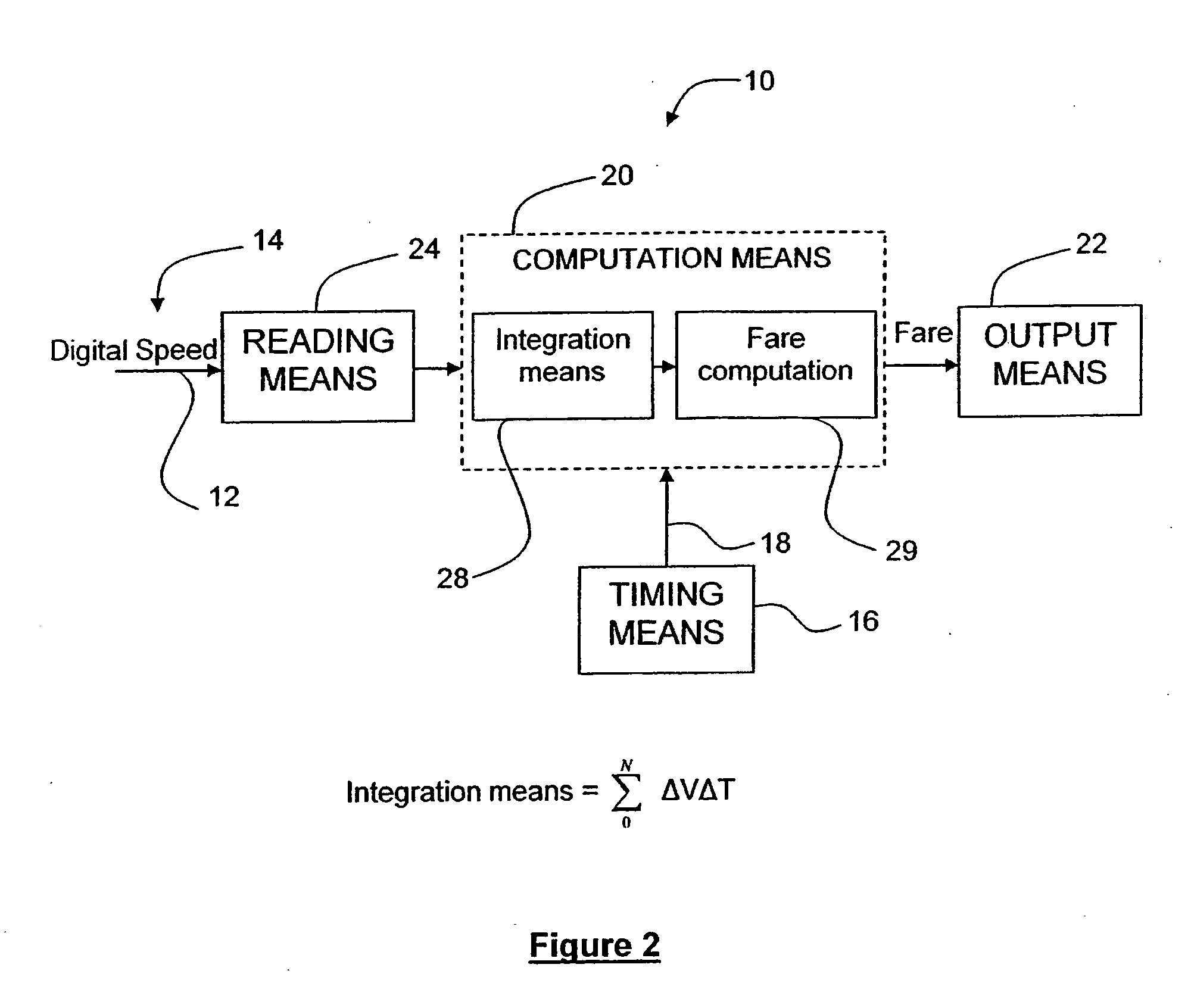
[0012]In a preferred embodiment, the digital data signal comprises digital speed data, the computation means having speed integration means f

Problems solved by technology

Although car manufacturers continue to use distance or speed pulse trains in some sub-systems such as ABS brakes, these signals have become difficult to access and in many cases, car manufacturers do not recommend hooking other devices to these signals.
There are at least three major issues with taximeters using pulse trains as signal input.
Firstly, locating and connecting to these pulse trains has become the most difficult part of a taximeter installation.
A second more serious problem has arisen from the fact that unscrupulous operators have found a way to cheat taxi passengers.
As a result, the meter needs to be calibrated to match the vehicle, which is generally a time consuming task.
Firstly, the taximeter input still consists of pulses and is therefore susceptible to external modification in order to cheat the customer.
Furthermore, the method is costly in that much of the circuitry required to read the bus is already used in the taximeter and is thus being duplicated.
Moreover, the digital signal on the bus is being converted to an analog waveform unnecessarily thereby introducing an additional source of inaccuracy since the meter (which is primarily a digital device) needs to convert it back to digital.
Additionally, the user has to install two devices instead of one, thereby adding complexity and cost to the installation.

Method used


Image

  • Taximeter using digital speed or distance as input
  • Taximeter using digital speed or distance as input
  • Taximeter using digital speed or distance as input

Examples


Embodiment Construction

[0018]In the following description, similar features in the drawings have been given similar reference numerals and in order to lighten the figures, some elements are not referred to in some figures if they were already identified in a preceding figure.

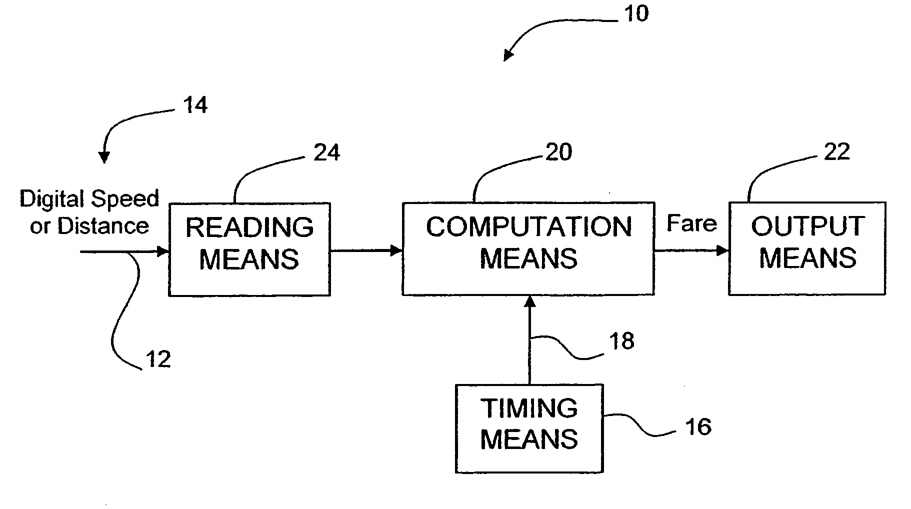
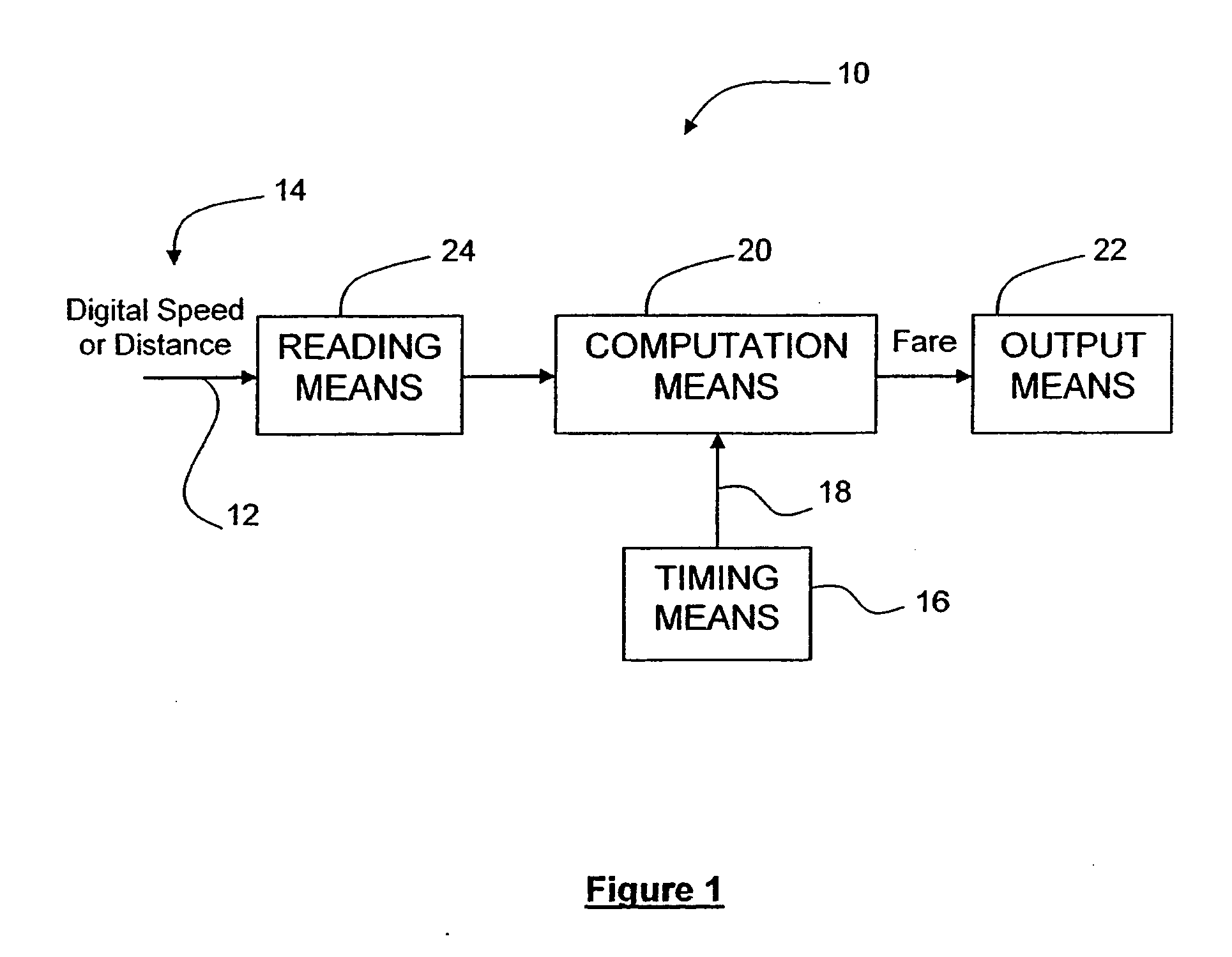
[0019]Referring to FIG. 1, there is shown an electronic taximeter 10 for a vehicle (not shown) using a serial bus multi bit digital data signal 14 providing one of speed data and distance data according to the present invention. The electronic taximeter 10, according to the invention, advantageously accepts a digital speed or distance signal at its input. Indeed, the taximeter 10 is provided with a digital input 12 for receiving one of the speed data and the distance data. The taximeter 10 has reading means 24 that are able to accept, read and interpret the digital input 12. The taximeter 10 is also provided with timing means 16 which provide timing data 18. The taximeter 10 also has computation means 20 operatively connected to the r...


PUM


Abstract

There is provided an electronic taximeter that accepts a digital data input representative of one of a vehicle speed and a distance traveled by the vehicle. The digital data signal may be taken from the electronic engine bus of the vehicle or from the On Board Diagnostic connector. The taximeter has reading means to read the digital data input, timing means to provide timing data and computation means operatively connected to the reading means and the timing means for computing a fare associated with a trip. The computation means can advantageously be provided with speed integration means for integrating the speed data with respect to time, or summation means where the input is a digital distance, in order to determine the distance traveled by the vehicle with an accuracy meeting the regulations.

Description

FIELD OF THE INVENTION[0001]The present invention generally relates to a taximeter used to compute the fare of a trip in a taxicab, and more particularly concerns an electronic taximeter particularly adapted to calculate the fare directly from a serial bus multi bit digital data signal corresponding to speed or distance data at its input.BACKGROUND OF THE INVENTION[0002]Taximeters generally compute fare based on a combination of distance traveled and elapsed time. The distance information is normally taken from a pulse train whose frequency is proportional to speed and each pulse therefore represents a fixed distance traveled.[0003]In the past, such pulse trains were readily available as car manufacturers provided them to be used by the speedometer and odometer among other things.[0004]Today with the dashboards going electronic, digital speedometers and odometers no longer use pulse trains as input signals. Although car manufacturers continue to use distance or speed pulse trains in...

Claims


Application Information

Patent Timeline
IPC IPC(8): G06F17/00G01C21/02
CPCG01C22/02G07B13/00G06Q30/0284
Inventor STEINER, PHILIP
Owner CENTDYNE
Learn More