
Recessed Luminaire

a technology of luminaires and recessed lights, applied in the field of luminaires, can solve the problems of difficult bulb aiming, process is made more troublesome, and the alignment process can be difficult, so as to minimize the opening size

Inactive Publication Date: 2008-05-15
FOCAL POINT
View PDF18 Cites 105 Cited by
  • Summary
  • Abstract
  • Description
  • Claims
  • Application Information

AI Technical Summary

Benefits of technology

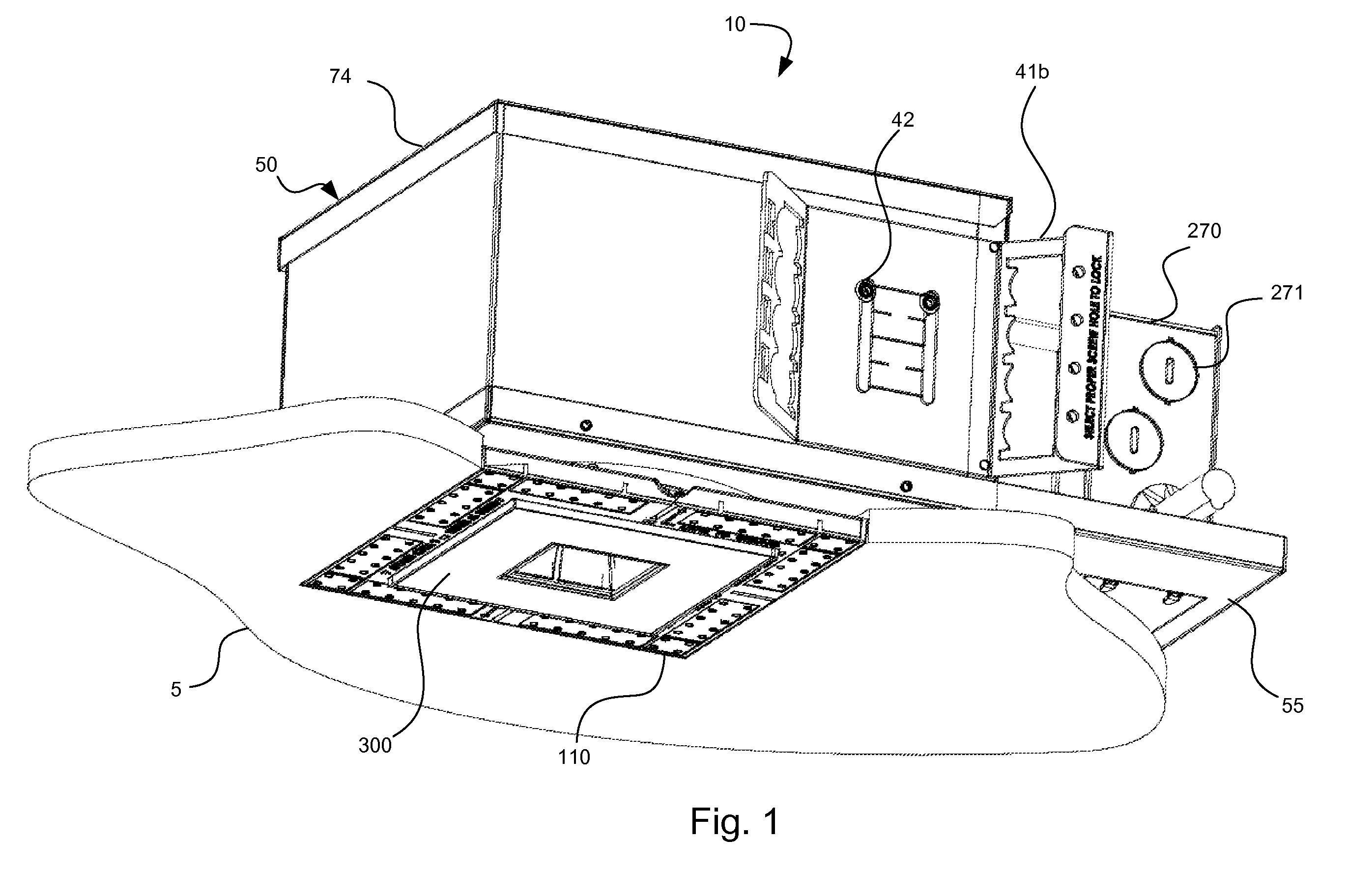
[0010]A recessed luminaire is provided. The luminaire may be mounted in a housing and the housing may support a transformer. The housing may be supported by adjustable supports that allow the housing to be positioned relative to a first side of a surface. An adaptor, which may be supported by the housing, may extend in an opening of the surface to or near a second side of the surface. The adaptor may be configured so as to allow its position to be adjusted separate from the housing so as to accommodate a range of surface thicknesses. The adaptor may be configured to be mudded or plastered into place so as to provide a substantially continuous surface appearance. The luminaire may include a trim plate that is configured to be partially disassembled from the luminaire and to hang out of the way. The luminaire may include an angle orientation feature. The luminaire may include a rotation adjustment feature. The luminaire may be configured to allow simultaneous adjustment of the angle orientation and rotation adjustment features and the luminaire may be configured to allow for adjustment while the bulb is on. The luminaire may include a locking feature that allows a bulb to be replaced without adjusting the aim or other desired settings of the luminaire during the bulb replacement while minimizing the size of the opening required.

Problems solved by technology

This alignment process can be difficult as the actual surface is not there when the housing is being aligned.
Current luminaires make it difficult to aim the bulb (or lamp) while the luminaire is on, thus adjusting the aim often requiring turning the power off, partially disassembling the luminaire, making an adjustment in the bulb aiming assembly, reassembling the luminaire and then turning the power back on to see if the adjustment correctly aimed the bulb in the desired direction.
This process is made more troublesome if one or more lens and / or filters are used to shape the light emitted from the bulb because often the lens and / or filters need to be carefully orientated.
Plainly, such a process is tedious and time consuming and thus expensive; however, such a process allows the luminaire to provide a variety of lighting effects in addition to down lighting, such as accent or wall-wash lighting.
Eventually the bulb in the luminaire will fail, either catastrophically or due to reduced light output, and will need to be replaced.
Current luminaires make it difficult to quickly change the bulb.
In addition, sometimes the luminaire must be partially disassembled when the bulb is changed, thus potentially modifying the aim of the luminaire that was previously painstakingly set.
As substantial time and money may have been invested in aiming the bulb at a particular point in the first place, modifying of the aiming of the bulb during the process of changing a bulb is generally undesirable.
As can be appreciated, this is a significant problem for installations where a larger number of luminaires are installed and each luminaire is separately aimed so as to provide a desired lighting effect.
However, current luminaires tend to allow or cause the filters to be inadvertently moved during the changing of the bulb, thus undesirably changing the effect the original light pattern was supposed to provide.

Method used


Image

  • Recessed Luminaire
  • Recessed Luminaire
  • Recessed Luminaire

Examples


Embodiment Construction

[0038]As is apparent from the Figures described above and the description provided below, various components are disclosed below and may be mounted to other components. Mounting may be direct or indirect and this disclosure is not intended to be limiting in this respect. It is noted that various component are described below as separate components. Two or more of these components may be combined to form a single component as appropriate and this disclosure is not intended to be limiting in this respect.

[0039]In addition, various features are described below in greater detail. It should be noted that different combinations of these features may be combined as desired to generate luminaires with more or less features, depending on the features that are needed. Thus, it is envisioned that additional luminaires using combinations of the below described features are within the scope of the present invention.

[0040]Certain embodiments of the present invention are directed towards a luminai...


PUM


Abstract

In an embodiment, a luminaire may include a housing that includes a support panel, a rotation ring supported by the support panel where the rotation ring is infinitely adjustable with a range of adjustments with respect to the support panel, a rotation drive unit configured to rotate the rotation ring with respect to the support panel, an aiming frame supported by the rotation ring, a tray system pivotally mounted to the aiming frame and configured to receive the bulb, and a tray drive configured to rotate the tray system about the pivotal mounting, whereby, in operation the rotational and angular orientation of the bulb may be adjusted while the bulb is on.

Description

CROSS-REFERENCE TO RELATED APPLICATIONS[0001]This applications claims priority to U.S. Provisional Application Ser. No. 60 / 865,832, filed Nov. 14, 2006, which is incorporated herein by reference in its entirety.BACKGROUND OF THE INVENTION[0002]1. Field of the Invention[0003]The present invention relates to the field of luminaires, more particularly to the field of luminaires that may be installed in a recessed manner.[0004]2. Description of Related Art[0005]Light fixtures or luminaires are commonly used in a variety of commercial and residential settings. While many types of luminaires exist, one popular type is a recessed bulb luminaire. The advantage of a recessed bulb luminaire, depending on the design, is that housing of the luminaire may be mounted in the ceiling or wall so that it does not noticeably extend beyond the mounting surface, thus providing a cleaner appearance when the luminaire is installed.[0006]A luminaire being installed in a ceiling is typically installed by fi...

Claims


Application Information

Patent Timeline
Patent Type & Authority Applications(United States)
IPC IPC(8): F21V19/02F21V15/00
CPCF21S8/02F21V14/02F21V19/02F21V21/14F21V21/29F21V21/30F21V21/04F21V23/001
Inventor PATTI, ANTHONY G.YUEN, STEPHEN H.THORNTON, PETER F.DOUBEK, DAVID E.
Owner FOCAL POINT
Learn More