
Paper feeder and image forming device

Inactive Publication Date: 2008-05-15
MURATA MASCH LTD
View PDF2 Cites 11 Cited by
  • Summary
  • Abstract
  • Description
  • Claims
  • Application Information

AI Technical Summary

Benefits of technology

[0008]In order to overcome the problems described above, preferred embodiments of the present invention provide a paper feeder, which makes it possible for a paper feed cassette not only to be pushed into and drawn out from a paper storage unit smoothly, but also makes it possible for the paper feed cassette to be maintained in a stable condition when stored in the cassette storage unit; and an image forming device including the same paper feeder.
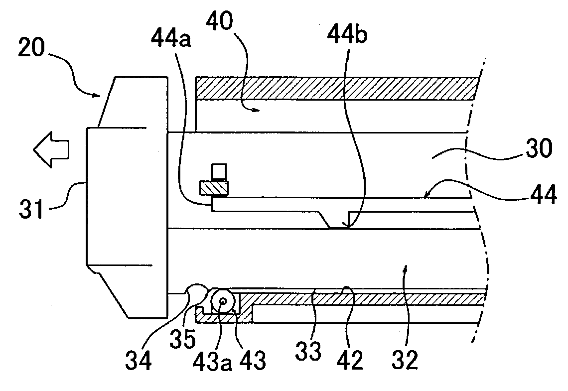
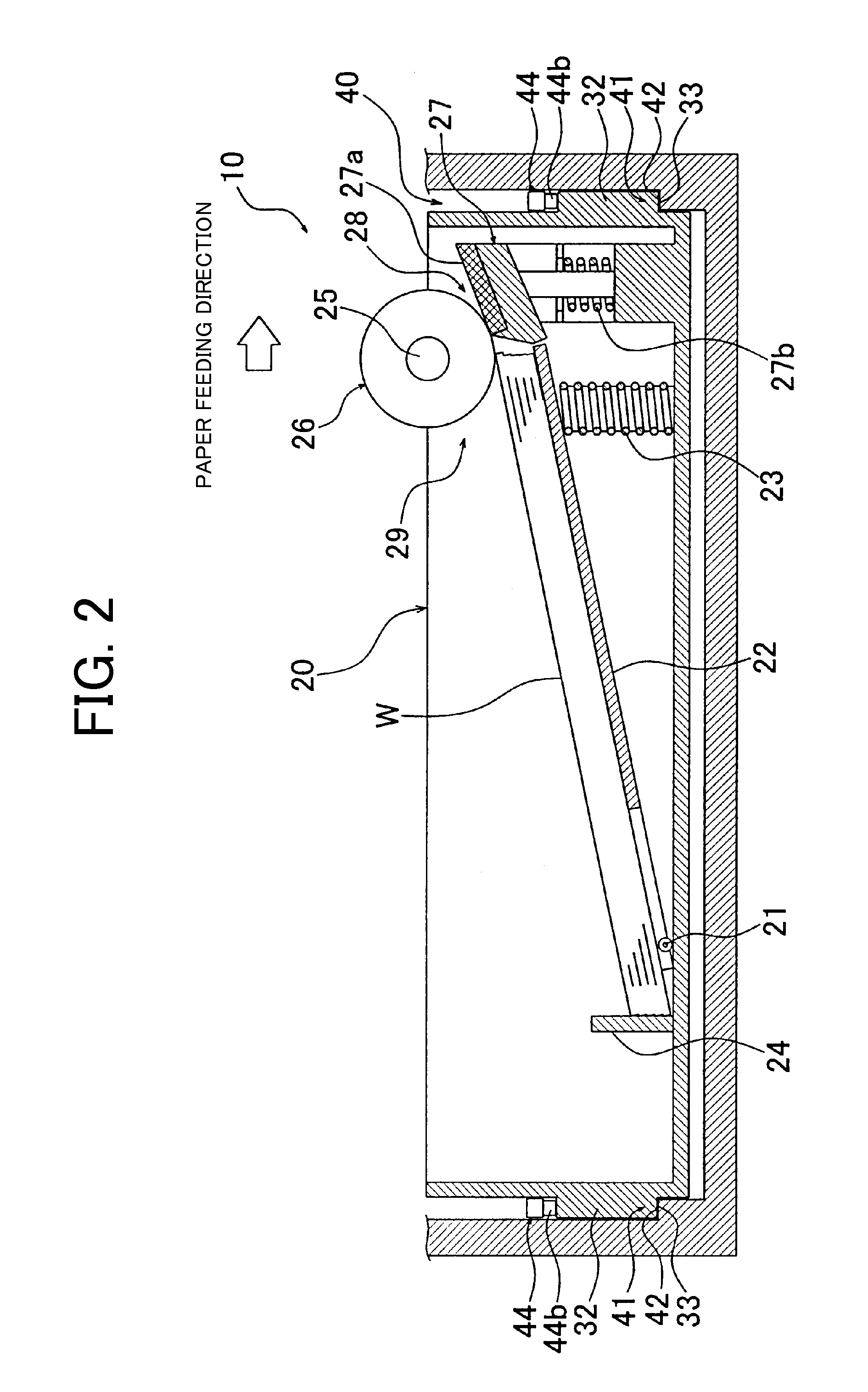
[0015]According to the above-described preferred embodiments of the present invention, the paper feeder is preferably configured such that when the paper feed cassette is moved along the storing direction thereof inside the cassette storage unit, the guide portion placed on the rotating member is slidably moved by the rotation of the rotating member. In the above-described paper feeder, the cassette storage unit includes the placement portion on which the guide portion is placed at the storage position where the paper feed cassette is stored in the cassette storage unit. Therefore, the paper feed cassette can be pushed in and drawn out smoothly by being slidably moved inside the cassette storage unit, and since the guide portion is placed on the placement portion, the paper feed cassette stored at the storage position can be maintained in the stable condition. Accordingly, oscillation of the paper feed cassette generated when the paper is transported inside the paper feed cassette can be effectively reduced.
[0016]According to the above-described preferred embodiments of the present invention, since the paper feeder is configured such that the guide portion is placed on the placement portion by surface contact, the paper feed cassette stored at the storage position can be maintained in a more stable condition, and the oscillation of the paper feed cassette can be reduced more effectively. Moreover, since the longitudinal size in the storing direction of the portion on which the guide portion is placed by surface contact is greater than the maximum width size in the storing direction of the paper accommodated inside the paper feed cassette, the oscillation can be prevented from being transmitted from the paper feed cassette to a full width of the transported paper, and the paper can be accurately transported.
[0017]According to the above-described preferred embodiments of the present invention, the paper feeder is configured such that the rotating member protrudes above the placement portion towards the guide portion side of the paper feed cassette and such that the paper feed cassette includes the rotating-member engaging portion to be engaged with the rotating member at the storage position. Therefore, when the paper feed cassette is moved inside the cassette storage unit, the guide portion is placed on the rotating member, and when the paper feed cassette is stored at the storage position, the guide portion is placed on the placement portion. Accordingly, with this simple configuration, the paper feed cassette can be slidably moved smoothly and also can be maintained stably at the storage position.
[0018]According to the above-described preferred embodiments of the present invention, in the paper feeder, since the rotating member is arranged on the rear side of the placement portion in the storing direction of the cassette storage unit, when pushing in and drawing out the paper feed cassette, the guide portion can be smoothly moved by the rotating member.
[0019]According to the above-described preferred embodiments of the present invention, the paper feeder includes the step portion arranged between the rotating-member engaging portion and the guide portion of the paper feed cassette such that the rotating member passes over the step portion when the paper feed cassette moves from the storage position. Accordingly, with this simple configuration, resistance can be applied to a force which moves the paper feed cassette when the paper feed cassette is pushed in and drawn out. Moreover, a possibility that the paper feed cassette stored at the storage position moves improperly can be reduced.

Problems solved by technology

As the oscillation of the paper feed cassette increases, there arises a possibility of affecting an image quality, etc., of an image that is recorded at the recording unit.
However, in the above-described moving mechanism, although the paper feed cassette can be smoothly pushed in and drawn out, sufficient measures have not been taken to maintain the paper feed cassette stored in the cassette storage unit in a stable condition.

Method used


Image

  • Paper feeder and image forming device
  • Paper feeder and image forming device
  • Paper feeder and image forming device

Examples


Embodiment Construction

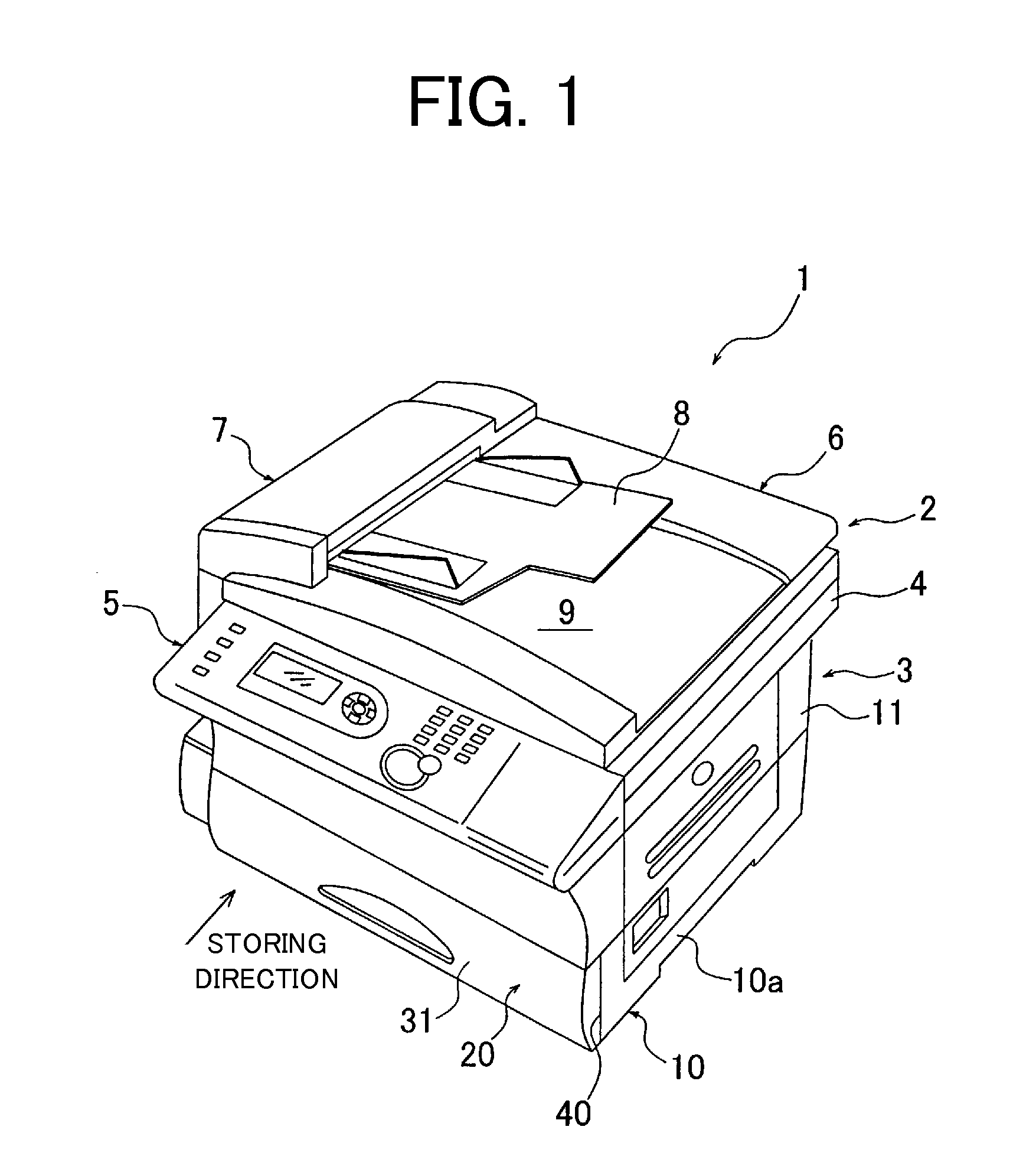
[0028]With reference to the drawings, preferred embodiments of the present invention will be described in detail. FIG. 1 is a perspective view illustrating an external-configuration example of an image forming device including a paper feeder according to a preferred embodiment of the present invention. First, with reference to FIG. 1, a description will be made of a schematic overall configuration of the image forming device. As long as the image forming device includes the paper feed cassette, the image forming device to which the present invention is applied may be any one of a copier, a facsimile machine, a printer, and / or a multi function peripheral having a coping function, a facsimile function, and a printer function, etc. An image forming device 1 illustrated in FIG. 1 includes a scanning unit 2 arranged on an upper side thereof and a recording unit 3 arranged on a lower side thereof.

[0029]The scanning unit 2 includes an image scanning device 4 arranged to read an image of an...


PUM


Abstract

A paper feeder includes a guide surface arranged on a paper feed cassette and a roller arranged on a cassette storage unit. When the paper feed cassette is moved along a storing direction thereof inside the cassette storage unit, the guide surface placed on the roller is slidably moved by rotation of the roller. In the paper feeder, since the cassette storage portion includes a placement surface on which the guide surface is placed by surface contact at a storage position where the paper feed cassette is stored in the cassette storage unit, the stored paper feed cassette can be maintained in a stable condition, and oscillation of the paper feed cassette generated when the papers are transported can be reduced.

Description

CROSS-REFERENCE TO RELATED APPLICATIONS[0001]This application claims priority under 35 U.S.C. 119 to Japanese Patent Application No. 2006-309611, filed on Nov. 15, 2006, which application is hereby incorporated by reference in its entirety.BACKGROUND OF THE INVENTION[0002]1. Field of the Invention[0003]The present invention relates to a paper feeder in which a paper feed cassette for accommodating papers is slidably moved inside a cassette storage unit when the paper feed cassette is pushed into and drawn out from the cassette storage unit, and also relates to an image forming device including the above-described paper feeder.[0004]2. Description of the Related Art[0005]A conventional image forming device such as a facsimile machine and a copier includes a paper feeder having a paper feed cassette for accommodating papers that are transported to a recording unit arranged to record an image. In the paper feeder, the paper feed cassette is stored in a drawer configuration in the casse...

Claims


Application Information

Patent Timeline
IPC IPC(8): B65H1/22A47B88/493
CPCB41J13/103B65H2405/31B65H2402/53B65H1/26B65H1/266
Inventor TANAKA, SATOSHISHIMAMOTO, HIDEATSU
Owner MURATA MASCH LTD
Learn More