Method of making an auto-calibrating test sensor
a technology of auto-calibrating and test sensors, which is applied in the field of making test sensors, can solve the problems of high cost of manufacturing millions of sensor packages, each having a calibration circuit or label to assist in calibrating the sensor package,
Inactive Publication Date: 2008-05-08
BAYER HEALTHCARE LLC
View PDF36 Cites 163 Cited by
- Summary
- Abstract
- Description
- Claims
- Application Information
AI Technical Summary
Benefits of technology
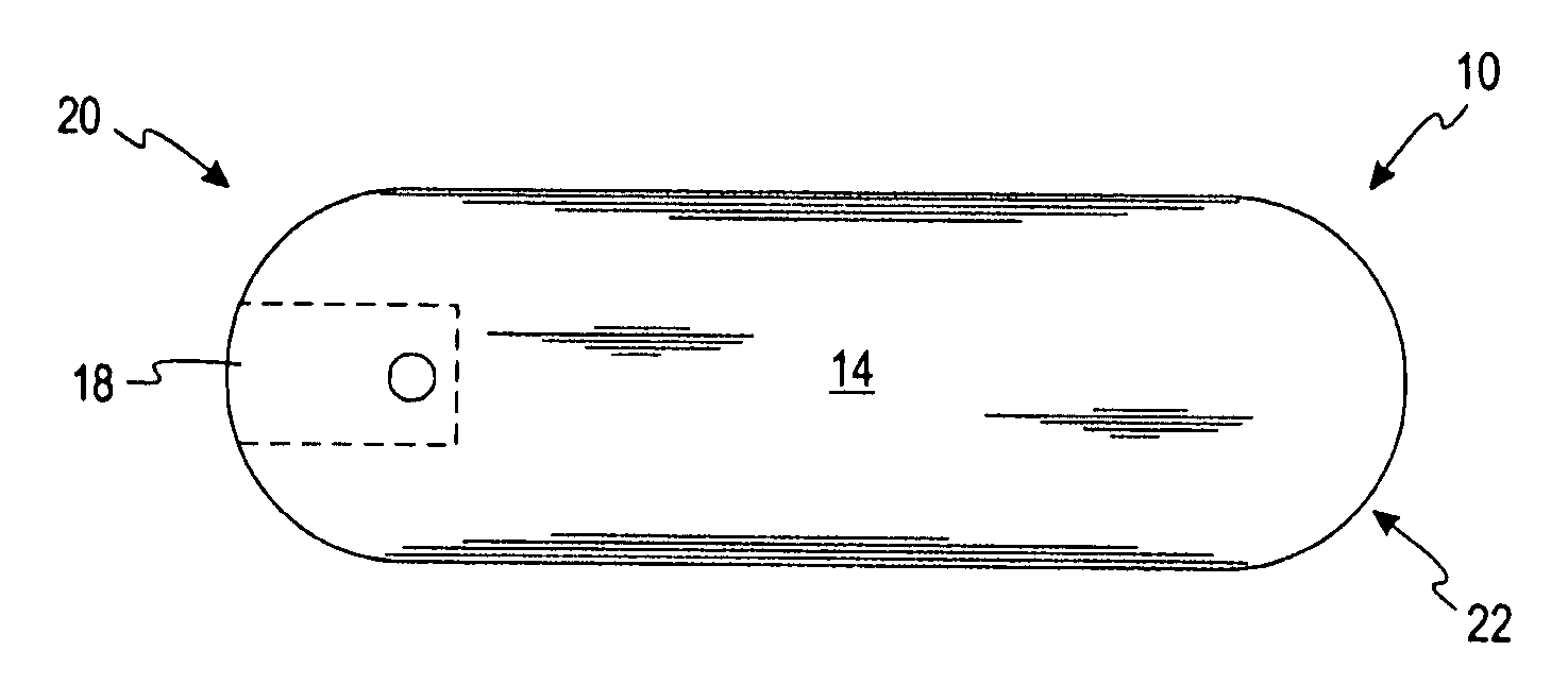
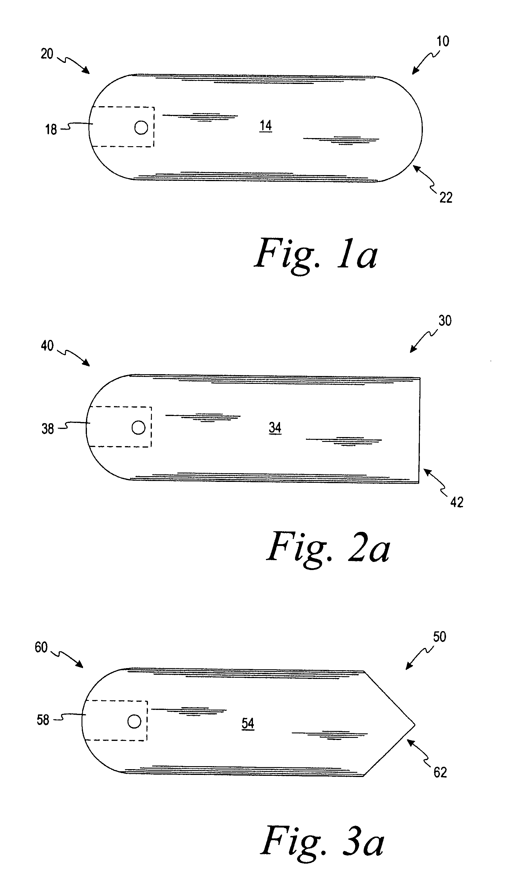
[0020]According to another embodiment, an optical test sensor is adapted to determine an analyte concentration of a fluid sample. The optical test sensor comprises a base, a fluid-receiving area and at least one reagent. The base includes a first base end and an opposing second base end. The fluid-receiving area is adapted to receive a fluid sample. The fluid-receiving area is located near or at the first base end. The at least one reagent is positioned to contact the fluid sample in the fluid-receiving area. The at least one reagent assists in optically determining the analyte concentration of the fluid sample. The optical test sensor includes a first end and an opposing second end. The auto-calibration area has non-conductive markings in a form of a pattern corresponding to auto-calibration information. The markings are adapted to be optically detected.
Problems solved by technology
Method used
View moreImage
Smart ImageViewing Examples

Examples
embodiment a4
[0340]The test sensor of embodiment YYY wherein the auto-calibration area is formed on the base at the opposing second base end.
embodiment b4
[0341]The test sensor of embodiment YYY further including a lid, the lid covering at least a portion of the base, the lid having a first lid end and an opposing second lid end.
embodiment c4
[0342]The test sensor of embodiment B4 wherein the auto-calibration area is formed on the lid.
Login to View More PUM
| Property | Measurement | Unit |
|---|---|---|
| width | aaaaa | aaaaa |
| width | aaaaa | aaaaa |
| concentration | aaaaa | aaaaa |
Abstract
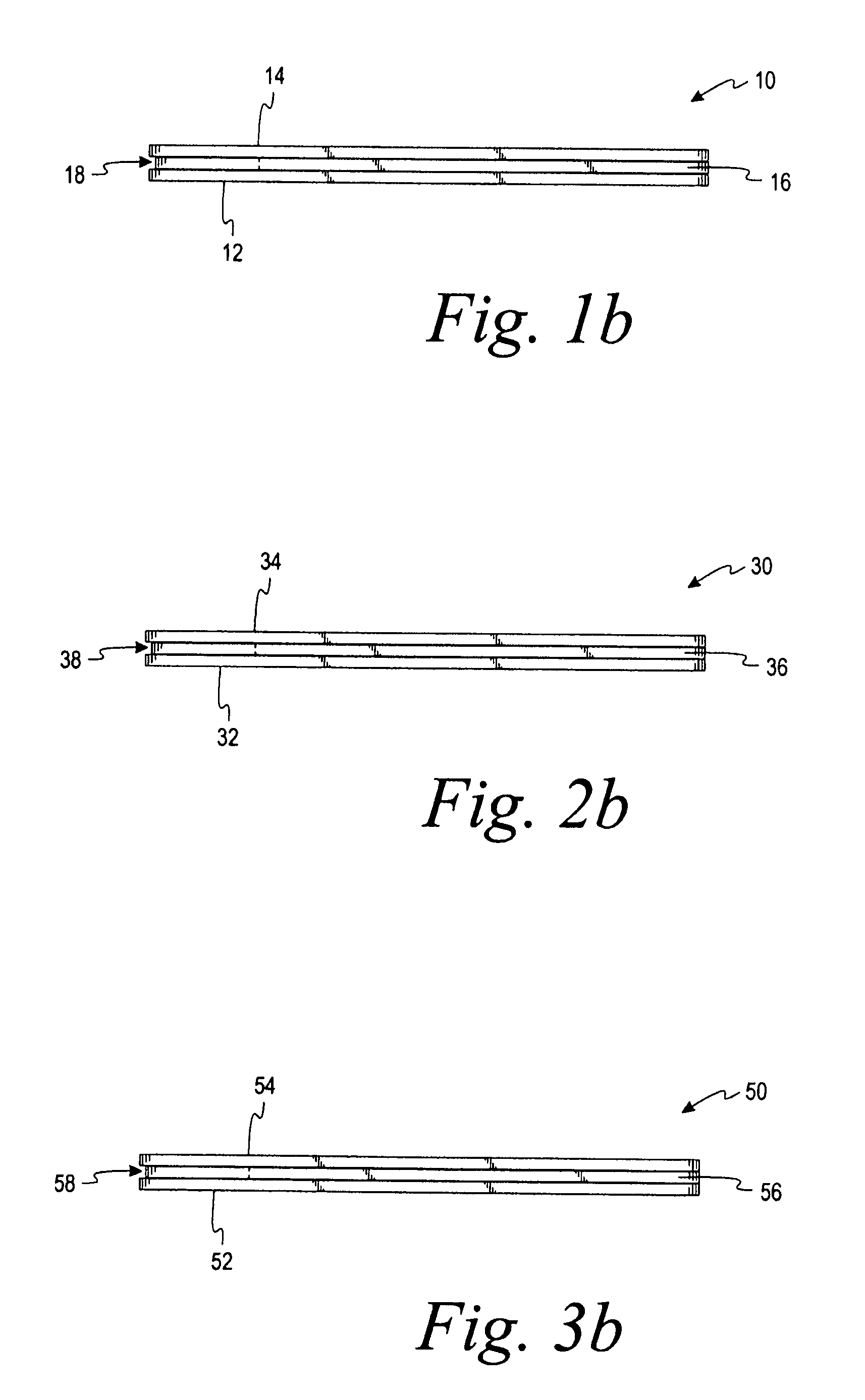
A test sensor is made that is adapted to assist in determining the concentration of an analyte in a fluid sample. The method includes providing a lid and providing a base. The lid is attached to the base to form an attached lid-base structure. The lid-base structure has a first end adapted to receive the fluid sample and a second opposing end adapted to be placed into a meter. Auto-calibration information is assigned to the lid-base structure. The second opposing end is formed such that the shape of the second opposing end corresponds to the auto-calibration information.
Description
CROSS-REFERENCE TO RELATED APPLICATIONS[0001]This application claims priority to U.S. Provisional Application Ser. Nos. 60 / 857,370 filed on Nov. 7, 2006 and 60 / 925,227 filed Apr. 18, 2007, which are incorporated by reference in their entirety.FIELD OF THE INVENTION[0002]The present invention generally relates to a method of making a test sensor that is adapted to determine an analyte concentration. More specifically, the present invention generally relates to a method of making an auto-calibrating test sensor.BACKGROUND OF THE INVENTION[0003]The quantitative determination of analytes in body fluids is of great importance in the diagnoses and maintenance of certain physiological abnormalities. For example, lactate, cholesterol and bilirubin should be monitored in certain individuals. In particular, it is important that diabetic individuals frequently check the glucose level in their body fluids to regulate the glucose intake in their diets. The results of such tests can be used to de...
Claims
Login to View More Application Information
Patent Timeline
 Patent Type & Authority Applications(United States)
IPC IPC(8): G01N21/00G01N27/00
CPCG01N21/274G01N21/278Y10T29/49004G01N33/48771G01N21/8483
Inventor CREAVEN, JOHN P.DOSMANN, ANDREW J.BRENNEMAN, ALLEN J.CHARLTON, STEVEN C.
Owner BAYER HEALTHCARE LLC
Features
- R&D
- Intellectual Property
- Life Sciences
- Materials
- Tech Scout
- Unparalleled Data Quality
- Higher Quality Content
- 60% Fewer Hallucinations
Learn More Browse by: Latest US Patents, China's latest patents, Technical Efficacy Thesaurus, Application Domain, Technology Topic, Popular Technical Reports.
© 2025 PatSnap. All rights reserved.Legal|Privacy policy|Modern Slavery Act Transparency Statement|Sitemap|About US| Contact US: help@patsnap.com