Method and apparatus for tracking objects over a wide area using a network of stereo sensors
a stereo sensor and object tracking technology, applied in the field of computer vision, can solve the problems of blob tracking, inability to distinguish one of the movable objects, and inability to track objects over a wide area
- Summary
- Abstract
- Description
- Claims
- Application Information
AI Technical Summary
Benefits of technology
Problems solved by technology
Method used
Image
Examples
example architecture
[0032
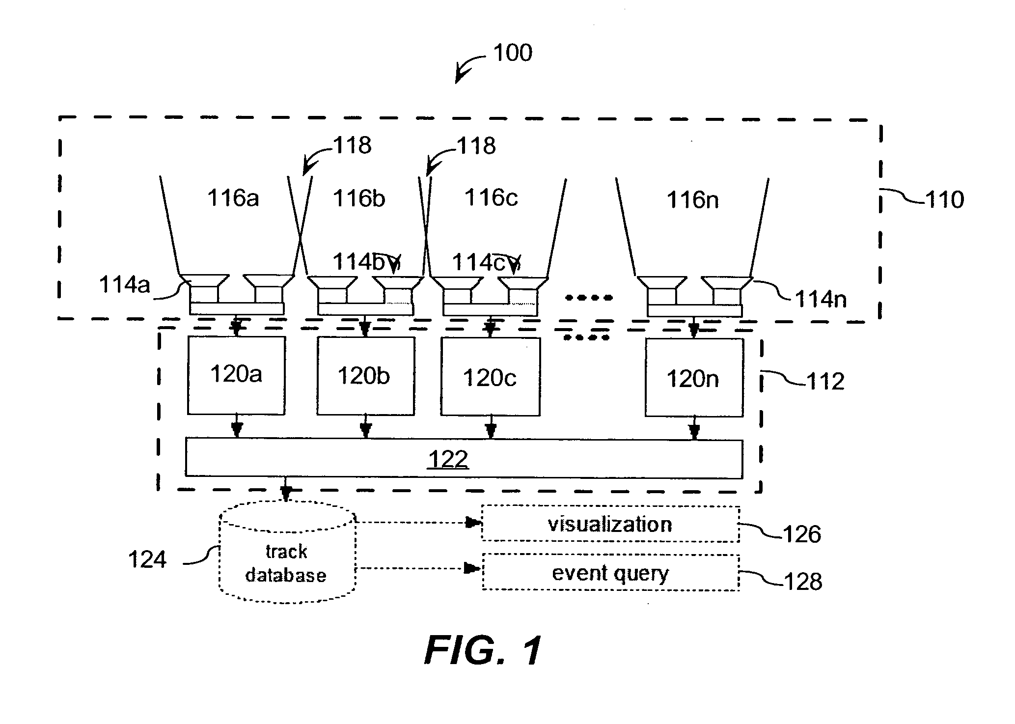
[0033]FIG. 1 is a block diagram illustrating an example of a system 100 that may be used to track one or more movable objects over a wide area. The system 100 may include a plurality or network of image sensors (“network”) 110, each of which is communicatively coupled to logic 112.
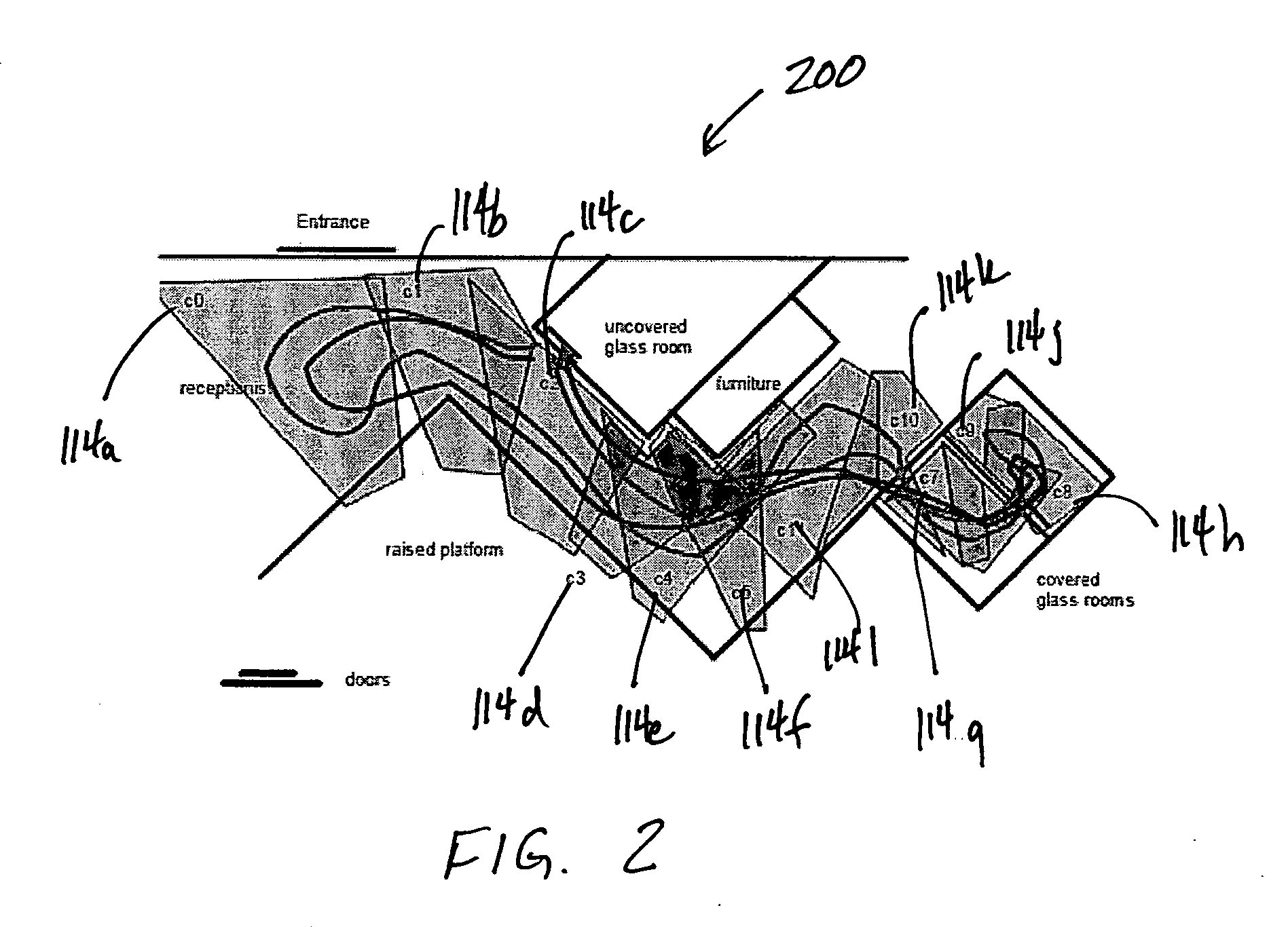
[0034]The wide area may be an area covering, for example, a part of a floor of a building (“building floor”) or any other area. FIG. 2 is a diagram illustrating an overhead view of a building floor 200. The building floor 200 includes two rooms and a large common area. The building floor 200 may include a number of challenges for tracking the movable objects. These challenges may include, for example, large TV displays with constantly changing appearance; the two rooms have IR-triggered lights installed that go on and off frequently; the two rooms have see-through glass walls; some of portions of the two rooms need to be monitored and others portions are excluded from being monitored; and the rooms ha...
example operation
[0053
[0054]FIG. 4 is a flow diagram illustrating a method 400 for tracking one or more movable objects over a wide area. Although the method 400 may be carried out by different architectures, the following is described with reference to the example system 100 of FIG. 1, for simplicity.
[0055]The method 400 starts at termination block 410 after each of the first and second sensors 114a, 114b capture within their FOVs 112a, 112b at least one respective image. As shown in process block 412, each of the first and second tracking modules 120a, 120b obtain the first and second images from the first and second stereo sensors 114a, 114b, respectively. To obtain the images, the first and second tracking modules 120a, 120b may query and receive them from the first and second sensors 114a, 114b or, alternatively, receive them without querying.
[0056]After obtaining the first and second images, the first tracking module 120a generates first and second local-track segments for first and second obj...
example single
[0064-Camera Processing
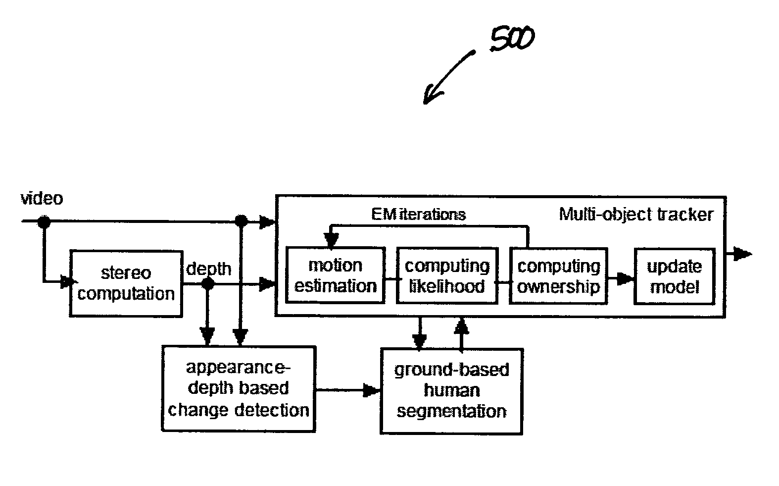
[0065]FIG. 5 is a block diagram illustrating an example of an object-representation process 500 for a single stereo sensor, such as any of the stereo sensors 114a-114n. The object-representation process 500 may be performed by any appropriate architecture, such as a standard personal computer without special purpose hardware in real-time, near real-time or otherwise contemporaneous with receiving, images captured by the stereo sensors 114a-114n. For convenience, however, the object-representation process 500 process 500 is described with reference to the architecture 100 in FIG. 1, and in particular to stereo sensor 114a, the tracking module 120a and the multi-sensor-fusion module 122.
[0066]The stereo sensor 114a, the tracking module 120a, and the multi-sensor-fusion module 122 may use a layer-based formulation for tracking objects, such as humans. In this layer-based formation, the stereo sensor 114a and the tracking module 120a perform a semi-3D object repre...
PUM
 Abstract
Description
Claims
Application Information
 - R&D
- Intellectual Property
- Life Sciences
- Materials
- Tech Scout
- Unparalleled Data Quality
- Higher Quality Content
- 60% Fewer Hallucinations
Browse by: Latest US Patents, China's latest patents, Technical Efficacy Thesaurus, Application Domain, Technology Topic, Popular Technical Reports.
© 2025 PatSnap. All rights reserved.Legal|Privacy policy|Modern Slavery Act Transparency Statement|Sitemap|About US| Contact US: help@patsnap.com


