
Lock/rotation mounted suppressor

a technology of rotating suppressor and locking mechanism, which is applied in the field of adaptors, can solve the problems of excessive play in attaching the suppressor, many technical difficulties still exist with the attachment of the suppressor to the firearm, and affect the accuracy of the firearm

Inactive Publication Date: 2008-05-01
BRUGGER KARL
View PDF13 Cites 32 Cited by
  • Summary
  • Abstract
  • Description
  • Claims
  • Application Information

AI Technical Summary

Problems solved by technology

However, many technical difficulties still exist with the attachment of the suppressors to the firearm.
One problem relates to the excessive play in attaching the suppressor.
While it is understood that the bore of the suppressor has to be accurately aligned with the bore of the barrel, excessive play often adversely affects the accuracy of the firearm.
Another problem is attachment of the suppressor without properly securing the suppressor on the firearm.
Suppressors that are not properly secured have a disturbing tendency to occasionally blow off of the firearm when the firearm fired.
Even suppressors that appear to be tightly secured may loosen during firing, causing too much play, and possibly causing the suppressor to be blown off.
Additional problems include taking too long to mount the suppressor on or remove the suppressor from the barrel.
For example, suppressors that are threaded directly on the barrel often require an inconveniently long time to screw the suppressor securely to the barrel or to unscrew the suppressor from the barrel.
Other methods and devices used to mount the suppressor are often too complicated or require the use of tools.

Method used


Image

  • Lock/rotation mounted suppressor
  • Lock/rotation mounted suppressor
  • Lock/rotation mounted suppressor

Examples


Embodiment Construction

[0013]The present invention is described below in considerable detail for particular embodiments for illustrative purposes only. It will be obvious to those skilled in the art that alterations may be made in the device itself or in the procedure for using the device without departing from the concept, scope and spirit of the present invention as described in the claims below. Finally, all references, including any priority documents, cited herein are hereby incorporated by reference.

[0014]For purposes of this disclosure, the term forward, fore and other similar terms will reference the direction from which a fired projectile will exit. The term rearward, rear and other similar terms will reference the direction from which a fired projectile will originate. The term permanently affixed or derivatives thereof refer to affixing a part in a manner that is difficult to reverse without damaging the part or the thing the part is affixed to. The phrase “excessive play is removed,” and other...


PUM


Abstract

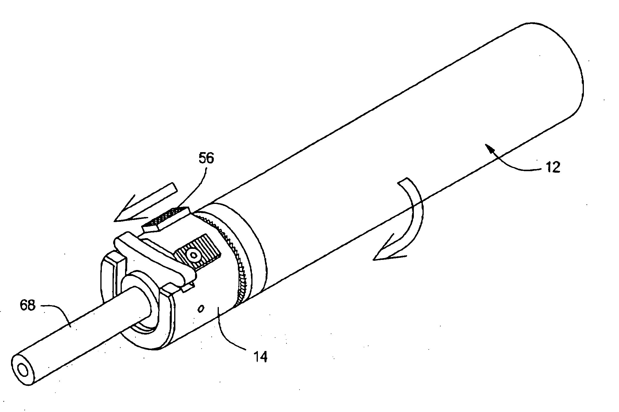
The present invention is directed to an adaptor for a suppressor comprising a gate for locking the suppressor on the muzzle and a threaded receiver for securing the suppressor to the firearm such that excessive play of the suppressor is removed. It is further directed to a method of securing a suppressor on a firearm by engaging a gate on an adaptor in a groove on a barrel of the firearm to lock on the adaptor, and any attached suppressor, and then tightening the suppressor and the adaptor on the barrel by threading the suppressor into the adaptor until excessive play is removed.

Description

PRIORITY INFORMATION[0001]The present application claims priority from and is a continuation-in-part of U.S. Provisional Patent Application 60 / 695,399 filed Jun. 30, 2005.BACKGROUND OF THE INVENTION[0002]The present invention relates to an adaptor for mounting a suppressor on a firearm, a method for mounting a suppressor on a firearm and a suppressor having the adaptor.[0003]Firearm noise and / or recoil suppressors are well-known. Some suppressors and devices to mount suppressors are disclosed in U.S. Pat. No. 3,710,679, U.S. 5,679,916, U.S. Pat. No. 6,302,009 B2, U.S. Pat. No. 6,412,389 B2, U.S. Pat. No. 6,701,820 B2 and U.S. Pat. No. 6,796,214 B2. However, many technical difficulties still exist with the attachment of the suppressors to the firearm. One problem relates to the excessive play in attaching the suppressor. While it is understood that the bore of the suppressor has to be accurately aligned with the bore of the barrel, excessive play often adversely affects the accuracy ...

Claims


Application Information

Patent Timeline
IPC IPC(8): F41A21/00
CPCF41A21/325F41A21/30
Inventor BRUGGER, KARL
Owner BRUGGER KARL
Learn More